Movement Joint Bridge Engineering: Seismic Integration & Lifecycle Performance
Modern bridge infrastructure is subject to a continuous spectrum of displacements: thermal expansion, concrete creep, live-load deflection, and—most critically—seismic events. A movement joint bridge (often referred to as an expansion joint) is not an isolated component; it operates within a dynamic system that includes elastomeric bearings, lead rubber bearings (LRBs), and fluid viscous dampers. For engineers and asset owners, understanding how these elements interact directly affects structural integrity, service life, and post-earthquake operability. This article provides a detailed examination of movement joint bridges through the lens of seismic compatibility, maintainability, and fatigue-resistant design, incorporating insights from KINGWORK’s engineering framework for high-demand infrastructure.

1. Displacement Demands on Movement Joint Bridges: Beyond Thermal Effects
While temperature-induced movement remains the primary specification parameter for expansion joints, a properly engineered movement joint bridge must accommodate multiple displacement types. These include:
Longitudinal movements – caused by uniform temperature changes, shrinkage, and creep in concrete girders.
Transverse & vertical movements – from wind loading, braking forces, and traffic-induced vibrations.
Rotational movements – due to differential settlement or girder end rotation under live loads.
Seismic-induced multidimensional displacements – horizontal (longitudinal + transverse) and vertical accelerations, often exceeding service-level displacement capacities by a factor of 3 to 5.
Conventional expansion joints designed solely for thermal demands often fail during moderate to strong earthquakes, leading to deck unseating, pounding damage, or joint lock-up. This is why a modern movement joint bridge must be evaluated under combined thermal + seismic displacement spectra. Industry standards (AASHTO, EN 1998-2) now require that joint displacement capacity be at least the maximum relative displacement from the seismic design scenario, including inelastic response of the substructure.
2. Synergy Between Movement Joints and Seismic Isolation Systems
Seismic isolation systems—such as lead rubber bearings (LRBs), high-damping rubber bearings, and concave sliding bearings—extend the natural period of the bridge and dissipate seismic energy. However, this increased flexibility also generates larger deck displacements relative to the substructure. A movement joint bridge that works in harmony with isolation bearings must satisfy three key requirements:
Accommodation of concentrated rotations at the joint gap – Isolators allow rigid-body translation, but the joint region must tolerate angular rotations without sealing damage.
Transverse & vertical seismic gaps – During a seismic event, a movement joint bridge should provide additional lateral and vertical clearance (often via oversized steel combs or modular systems) to prevent contact between adjacent decks or between deck and abutment backwall.
Damping integration – Fluid viscous dampers placed adjacent to the joint reduce the relative velocity between deck ends, lowering impact forces on the joint’s edge beams and sealing elements. Field data from post-earthquake inspections confirm that dampers extend the fatigue life of modular expansion joints by more than 40% under near-fault ground motions.
KINGWORK has developed integrated design protocols for movement joint bridges paired with LRB and damper systems. One example includes specifying a multi-directional modular joint with reinforced edge beams and elastomeric seal profiles that can accommodate ±300 mm longitudinal, ±50 mm transverse, and ±30 mm vertical seismic displacements without loss of watertightness. This synergy prevents unseating and allows the bridge to remain passable for emergency vehicles after a design earthquake.
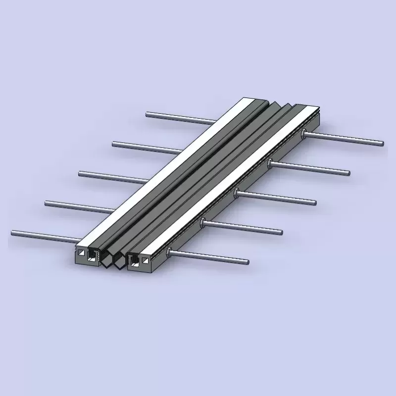
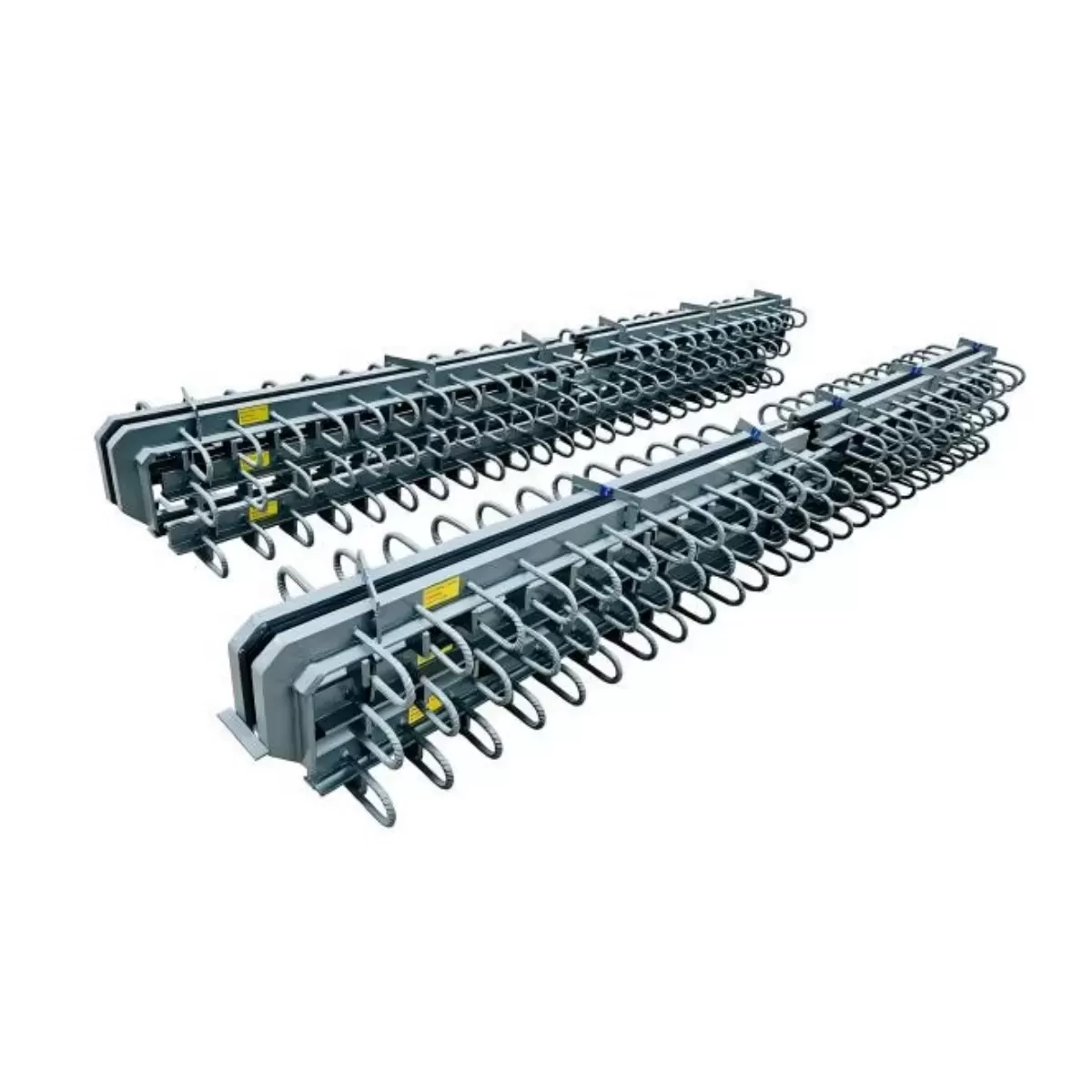
3. Comparative Analysis of Movement Joint Types: Performance Parameters
Selecting the optimal movement joint bridge type requires matching displacement capacity, sealing durability, maintainability, and seismic compatibility. The table below provides an updated comparison of four common joint categories used in medium- to long-span bridges, focusing on parameters that directly impact structural reliability and life-cycle performance.
| Joint Type | Movement Capacity (mm) | Watertightness Class (EN 1492) | Seismic Displacement Compatibility | Seal Replacement Method |
|---|---|---|---|---|
| Modular (multiple elastomeric seals) | 200 – 2000+ | Class A – zero leakage under 0.5 m head | Excellent (multi-directional + built-in shear bars) | Individual seal change; no full joint removal |
| Finger / comb joint with sliding plate | 100 – 800 | Class B – minor weepage allowed | Good for longitudinal seismic; limited transverse | Tooth plates must be partially unbolted |
| Strip seal (single or double gland) | 40 – 120 | Class A – watertight if gland undamaged | Poor – seal extrusion under high rotation | Full gland extraction & insertion from access pit |
| Buried / asphaltic plug joint | up to 50 | Class C – frequent leakage after 3–5 years | Not recommended (binder brittle at low temp) | Full demolition and repouring |
For seismic isolated bridges where total expected displacement may exceed ±400 mm, only modular movement joint bridges or heavy-duty finger joints with sliding bearings provide adequate capacity. The modular design also offers the advantage of replacing individual elastomeric seals without removing the entire assembly—an essential feature for minimizing traffic disruption during repair cycles. Additionally, watertightness class A (zero leakage) is strongly preferred for structures over environmentally sensitive areas or with high de-icing salt exposure.
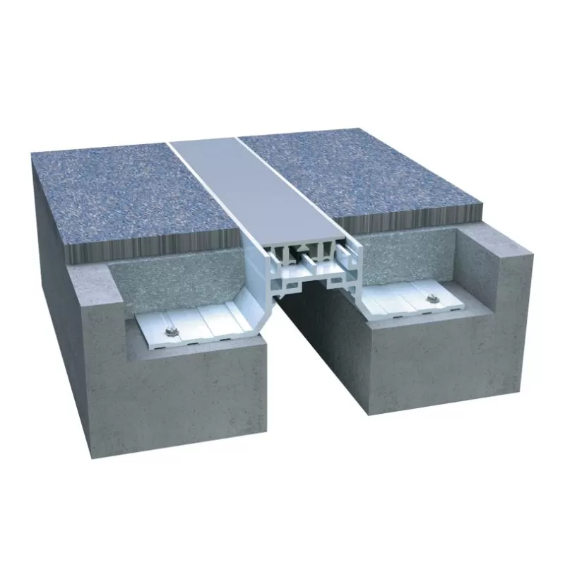
4. Water-Tightness, Wear Resistance, and Fast-Replaceable Seals
One of the highest maintenance costs for any movement joint bridge arises from water leakage through damaged seals. Water ingress causes corrosion of girder ends, bearing assemblies, and substructure concrete. To address this, modern joint systems employ:
Pre-compressed elastomeric seals (silicone or EPDM) with a shore hardness of 65–75 A, providing continuous contact pressure up to 0.5 bar.
Wear-resistant sliding surfaces – Ultra-high molecular weight polyethylene (UHMWPE) or bronze-impregnated PTFE plates attached to support bars, reducing friction and preventing steel-to-steel abrasion.
Watertight drainage channels integrated into the joint trough, directing any seepage away from critical components.
Fast-replaceable rubber seal design – Allows a two-person crew to extract and install a new seal within 2 hours per linear meter, using a manual roller insertion tool. No need to remove the edge beams or support bars. This “topside replacement” method reduces lane closure time by 70% compared to conventional bolted systems.
KINGWORK’s KF-200 modular movement joint bridge incorporates a patented quick-lock edge profile: the rubber seal is held by a dovetail groove and a stainless-steel spring clip, enabling replacement without heavy machinery. This design directly addresses asset owner requirements for low life-cycle disruption and high watertightness reliability.
5. Life-Cyle Performance Factors for Movement Joint Bridges
From a long-term asset management perspective, the service life of a movement joint bridge is defined not only by steel strength but by the durability of its sealing and sliding components. Three measurable metrics define life-cycle performance:
Seal fatigue resistance – Accelerated laboratory tests (ASTM D813) applying 1,000,000 cycles at 50% of max movement range should show no crack propagation >5 mm.
Corrosion protection of joint trough and edge beams – Hot-dip galvanizing + epoxy coating (minimum 300 µm thickness) extends first maintenance intervention beyond 25 years in de-icing salt environments.
Accessibility for inspection – Designs that include a removable cover plate over the joint gap allow visual inspection of the support bar and bearing pads without lifting the joint assembly.
Operational efficiency is further improved by modular joints that allow staged seal replacement (one seal at a time) while the adjacent lane remains open. This phased maintenance approach is now specified by highway authorities for high-ADT bridges.

6. Selection Criteria: Integrating Seismic Demands into Movement Joint Specs
When specifying a movement joint bridge for a region of moderate to high seismicity, engineers must revise the standard displacement calculation. A robust selection protocol includes:
Step 1 – Determine the maximum thermal + shrinkage + creep displacement (DLE – service level).
Step 2 – Perform nonlinear response-history analysis for the design basis earthquake (DBE). Extract the peak relative deck displacement at the joint location (including inelastic bearing deformation).
Step 3 – Select a joint type whose movement capacity ≥ 1.2 × (thermal displacement + DBE displacement). The 20% margin accounts for rotational incompatibility and unforeseen ground motion directionality.
Step 4 – Verify that the joint’s end beams and anchor plates can transfer seismic shear forces (typically 150–250 kN/m) to the deck end diaphragm. Use headed studs or cast-in channels, not post-installed anchors, for seismic zones.
Step 5 – Confirm that the joint’s transverse gap remains ≥ 50 mm after installation to prevent pounding during transverse seismic motion.
Employing these criteria ensures that the movement joint bridge does not become the weak link in the seismic force path—a principle embedded in KINGWORK’s engineering documentation for isolated bridges.
Reliability Through Integrated Design
The movement joint bridge is far more than a gap filler; it is a safety-critical interface between structural segments. When designed in concert with seismic isolation bearings and dampers, it protects the deck from collision stresses while maintaining a water barrier and a smooth ride surface. Advanced features—wear-resistant sliding plates, fast-replaceable elastomeric seals, and damage-tolerant steel modules—reduce long-term ownership burdens. For infrastructure owners requiring expert-engineered joint systems that respect both displacement capacity and seismic compatibility, specialized manufacturers provide tailormade solutions.
For project-specific recommendations, detailed shop drawings, or technical data on movement joint bridges integrated with seismic control devices, send an inquiry to the KINGWORK bridge engineering team. Our experts provide load-rating calculations, installation supervision guides, and life-cycle maintenance plans for any joint type—from strip seals to large-modular systems.
Frequently Asked Questions (FAQ) – Movement Joint Bridge Engineering
Q1: What is the difference between a movement joint bridge and a
standard expansion joint?
A1: While often used
interchangeably, a movement joint bridge specifically refers to the complete
assembly that accommodates cyclic displacement between two bridge decks or
between deck and abutment. Standard “expansion joints” may only address thermal
movement, whereas a movement joint bridge is designed for combined mechanical,
thermal, and seismic displacement demands, including multidirectional rotation
and shear transfer.
Q2: Can a modular movement joint bridge accommodate seismic
displacements without damage?
A2: Yes, if specified
correctly. Modular joints with multiple elastomeric seals and sliding support
bars can tolerate longitudinal displacements up to ±1000 mm and transverse
movements up to ±100 mm. However, the joint’s edge beams must be anchored into
reinforced concrete diaphragms with seismic detail (closed stirrups, sufficient
development length). For very large transverse displacement, a finger joint with
transverse sliding gaps is preferred.
Q3: How often should the rubber seal of a movement joint bridge be
replaced?
A3: Under normal highway traffic and
moderate climate conditions, high-grade EPDM or silicone seals provide 15–20
years of service life. In heavy de-icing salt or extreme UV exposure,
replacement intervals drop to 8–12 years. Systems designed for fast replacement
(like the KINGWORK quick-lock profile) reduce labour and lane closure time by
70% compared to bolted seals, making replacement cost-efficient even at shorter
intervals.
Q4: Do seismic isolation bearings increase the required movement
capacity of the joint?
A4: Definitely. Isolated
bridges experience larger deck displacements relative to the substructure
because the bearings decouple the deck from ground motion. A non-isolated bridge
might have a maximum displacement of ±80 mm under DBE; with LRB isolators, the
same bridge could reach ±300 mm at the joint location. Therefore, engineers must
recalculate the movement joint bridge rating based on the isolated displacement
response spectrum.
Q5: What design features improve watertightness of a movement joint
bridge over the long term?
A5: Three features are
essential: (i) A pre-compressed continuous seal with memory retention (minimum
compression set of 25%); (ii) stainless steel edge channels that prevent seal
extrusion; (iii) a drainage system that collects any leakage through a secondary
trough. Additionally, the seal should be replaceable without dismantling the
steel structure to avoid re-alignment issues. Many modern joints also include an
inspection port to verify seal seating after installation.
For detailed specifications or to discuss your bridge project’s movement joint requirements, please contact KINGWORK’s engineering support desk directly. We respond to all technical inquiries within 24 hours.