Friction Pendulum Bearing: Key Advantages & Trust Drivers
The Engineering Distinction: A Physics-Based Solution
The superiority of the Friction Pendulum Bearing (FPB) stems not from incremental improvement, but from a foundational difference in its operational philosophy. It replaces passive material deformation with an active, physics-governed sliding mechanism. This translates into a suite of provable, deterministic, and user-controlled advantages that directly address the most critical concerns in seismic and thermal design of heavy infrastructure.
1. Intrinsically Predictable and Tunable Performance
Technical Superiority: The FPB’s behavior is governed by a simple, physics-based equation: the restoring force is a direct function of its Radius (R), Friction Coefficient (μ), and the supported Weight (W). This parametric design means performance is not estimated from batch testing; it is calculated and guaranteed from first principles. Engineers are not selecting a component from a catalog; they are defining its exact properties to achieve a target isolated period and damping ratio for their specific structure.
User Trust Driver: This calculability eliminates performance guesswork. You can precisely model the force-displacement response in analysis software with high confidence, knowing the as-built bearing will match the model. It transforms seismic isolation from an "applied product" into an "engineered outcome," substantially reducing design liability and uncertainty.
2. Gravity-Powered, Fail-Safe Re-Centering
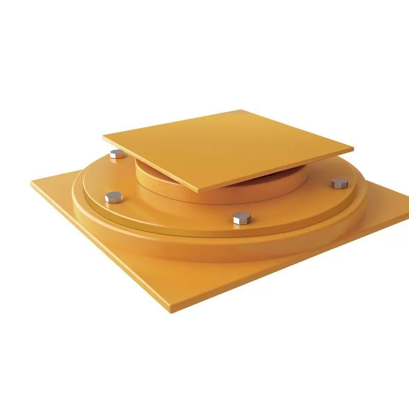
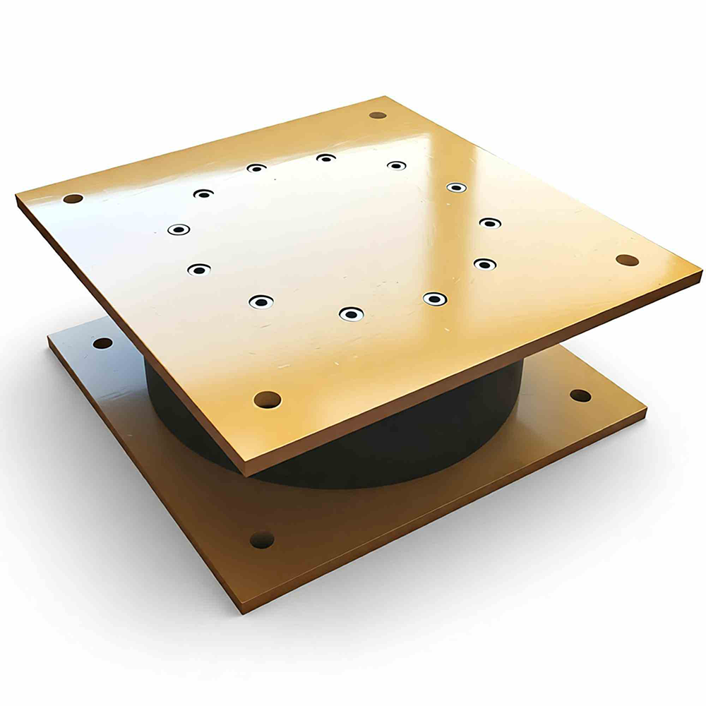
Technical Superiority: The concave spherical surface provides a unique inherent self-centering force derived from gravity (F = W * displacement / R). After any seismic displacement, this force automatically guides the structure back toward its original neutral position. Unlike systems requiring elastomeric strain energy or supplemental devices to re-center, the FPB’s mechanism is passive, fundamental, and failsafe.
User Trust Driver: This feature ensures zero residual displacement after an earthquake, a critical factor for maintaining bridge alignment, serviceability, and immediate functionality for emergency response. It provides assurance that the isolated structure will be ready for aftershocks and will not require costly realignment or bearing replacement post-event.
3. Unmatched Displacement Capacity & Stability
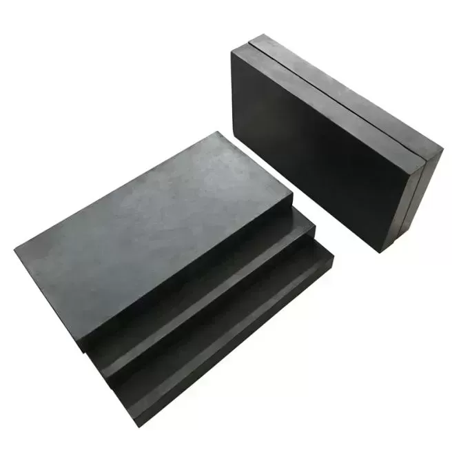
Technical Superiority: The FPB is engineered for extreme displacements (often > ±1000mm) where other isolators become impractical or oversized. Its sliding action is stable at any point within its range, without the risk of stiffness hardening or instability associated with large-strain rubber behavior. The combination of stainless steel and specialized polymer composite ensures a wear-resistant, low-maintenance interface with consistent friction properties across decades.
User Trust Driver: For projects in high seismic zones, near fault lines, or with significant thermal movement demands, the FPB provides a single, robust solution. It delivers certainty for the most demanding displacement scenarios, protecting investments in long-span bridges, tall structures, and infrastructure on soft soil sites where movement is inevitable and large.
4. Design Simplicity Leading to Robust Reliability
Technical Superiority: The mechanism has few moving parts—a slider on a curved surface—minimizing potential failure modes. There is no viscous fluid to leak, no lead core to fatigue, and no complex mechanical linkages. Performance is largely temperature and velocity insensitive due to the carefully engineered material pairing, ensuring consistent response in diverse climates and under varying seismic frequencies.
User Trust Driver: This inherent simplicity translates directly into exceptional long-term reliability and minimal lifetime maintenance. Owners and operators gain peace of mind knowing the system requires no scheduled servicing, fluid replacement, or specialized inspections, drastically reducing lifecycle costs and operational complexity.
5. Universally Compliant and Validated Durability
Technical Superiority: FPB design is backed by extensive accelerated wear-cycle and aging testing that validates performance stability over the full design life. The product is engineered to meet and exceed the world's most stringent seismic design codes, ensuring global applicability and acceptance by regulatory authorities.
User Trust Driver: Full compliance with major international standards provides a verifiable foundation for regulatory approval and project acceptance. This includes:
Americas: AASHTO Guide Specifications for Seismic Isolation Design, ASCE/SEI 7, IBC, Canadian Highway Bridge Design Code (CHBDC)
Europe & International: EN 15129 (Anti-seismic devices), ISO 22762 (Elastomeric seismic-protection isolators - relevant sections), Eurocode 8
Asia-Pacific: GB/T 20688 (China), JSHB (Japan Specifications for Highway Bridges)
General Building Codes: International Building Code (IBC), Uniform Building Code (UBC)
This comprehensive compliance portfolio eliminates approval hurdles and assures all stakeholders of the product's legitimacy, proven engineering, and successful deployment in major infrastructure projects worldwide.
Summary: The Confidence Equation
The Friction Pendulum Bearing offers more than seismic isolation; it provides a foundation for engineering and financial confidence.
For the Designer/Specifier: It is a tunable analytical tool that delivers predictable results, simplifies complex bridge movement issues, reduces professional risk, and is supported by globally recognized standards.
For the Project Owner/Operator: It is a long-term risk mitigation asset that ensures operational resilience, minimizes life-cycle maintenance, protects critical capital infrastructure from functional failure, and is backed by a robust framework of international code compliance.
For All Stakeholders: It represents the application of elegant, fundamental physics to solve modern engineering's most daunting challenges, offering a solution whose reliability is as certain as the gravity that powers it, and whose acceptance is validated by the world's leading engineering standards.
In an era where resilience is paramount, the FPB moves beyond protecting a structure from damage to guaranteeing its continued function—a decisive advantage that builds lasting trust on a foundation of proven science and global engineering consensus.
Friction Pendulum Bearing: Installation & Construction Methodology
Engineering for Practical Implementation
The Friction Pendulum Bearing (FPB) system is engineered not only for superior seismic performance but also for streamlined field implementation. Our approach transforms advanced seismic technology into a practical, constructible building component through meticulous planning, standardized procedures, and comprehensive technical support. The installation methodology is designed to integrate seamlessly with conventional construction practices while ensuring the precise performance characteristics required for seismic isolation.
Pre-Installation: Systematic Preparation and Planning
Design Coordination Phase
Before the first bearing arrives on site, our engineering team engages in detailed coordination with your project stakeholders. We provide complete installation method statements, sequence diagrams, and interface specifications that integrate with your construction schedule. Each bearing is custom-designed for its specific location, with unique identification markings and corresponding installation drawings.
Site Readiness Verification
We establish clear requirements for supporting structures:
Surface Tolerance: Concrete or steel bearing seats must meet flatness tolerances of 1/500 and elevation accuracy within ±3mm
Pre-Installation Survey: Verification of actual as-built conditions versus design drawings
Access and Logistics Planning: Clear paths for bearing delivery, positioning, and temporary storage
Material and Documentation Package
Each bearing ships as a complete, pre-assembled unit with:
Protective shipping restraints and environmental covers
Complete as-built documentation and material certifications
Specialized installation hardware and alignment tools where required
Step-by-step visual installation guide
Installation Process: Precision Execution
Stage 1: Positioning and Temporary Support
The bearing is positioned using standard crane equipment, guided by survey-controlled reference points. Temporary support jacks or shims maintain exact elevation and alignment during the connection phase. This phase requires no specialized equipment beyond standard construction tools.
Stage 2: Final Connection and Alignment
For Bolted Connections: High-strength bolts are installed following a specific torque sequence and value provided in the installation manual. This ensures uniform load distribution and prevents distortion of the bearing components.
For Welded Connections: Qualified welders follow pre-approved welding procedure specifications (WPS) to attach the bearing to embedded plates. Pre-heat and interpass temperature controls are specified as needed.
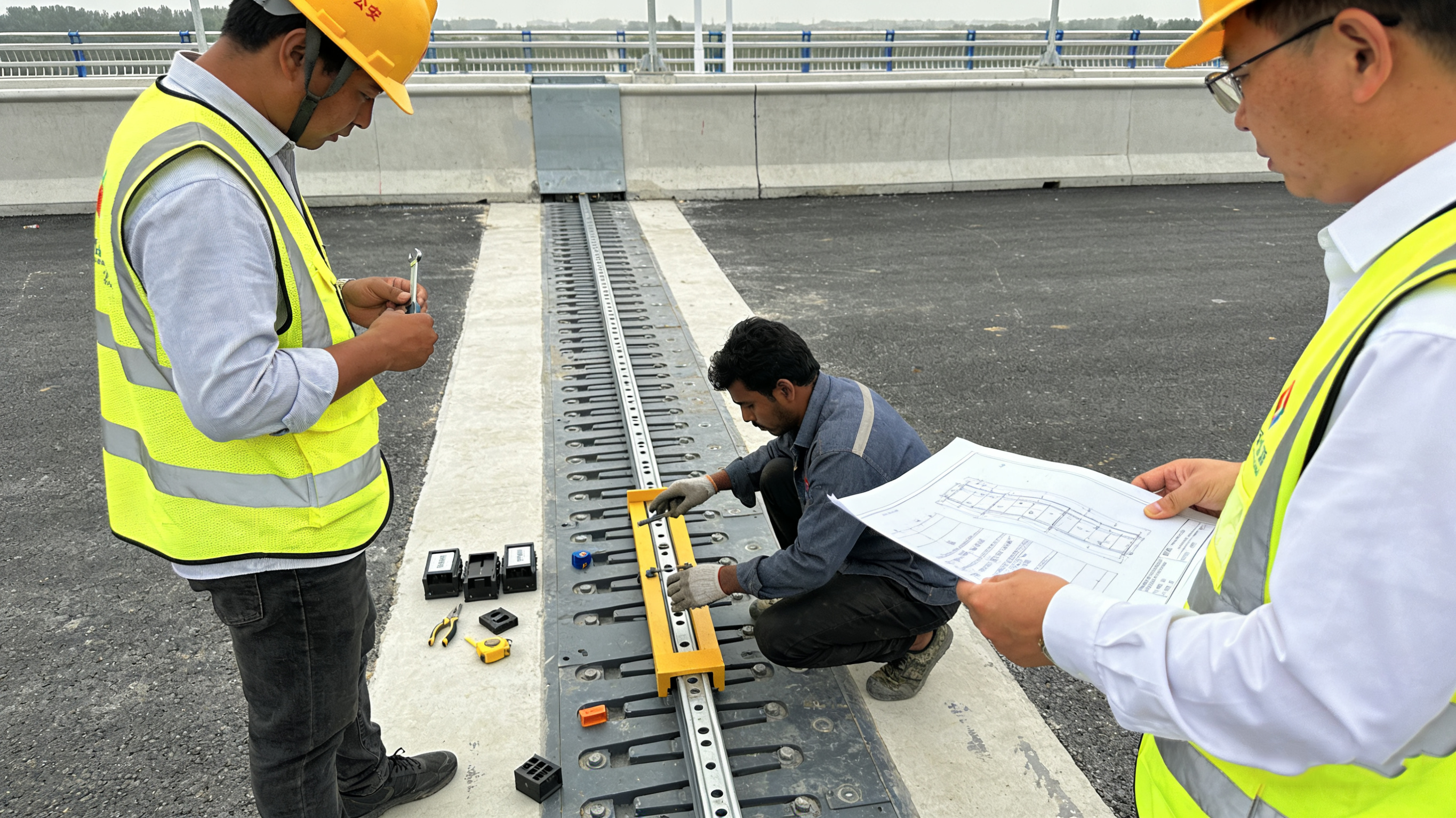
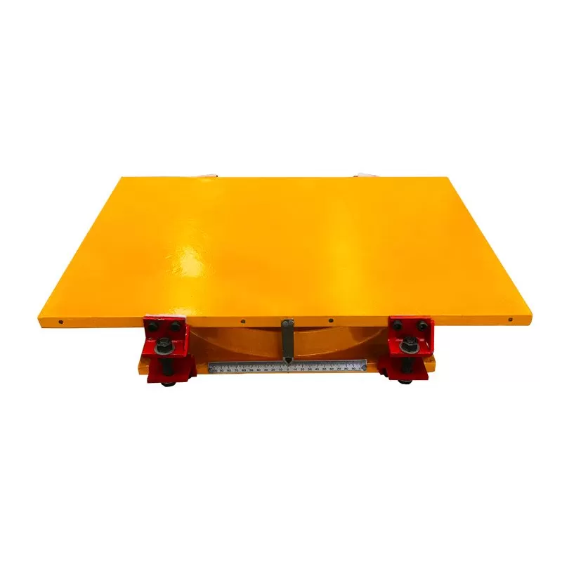
Real-Time Alignment Monitoring: Survey equipment continuously verifies position and level during connection to maintain tolerances.
Stage 3: Seismic Gap Verification and Commissioning
Once secured, the required seismic clearance around the bearing is verified to be free of permanent obstructions. Temporary shipping restraints are removed according to a specified sequence, typically after the superstructure is completed and the bearing is under full design load.
Technical Superiority in Field Implementation
No Special Curing or Setting Time
Unlike some foundation elements, FPBs require no curing time, chemical setting, or post-installation adjustments. Once installed and connected, they are immediately ready to accept design loads and perform their function.
Integrated Protection Systems
The bearing's environmental seals and protective covers are designed for easy installation during the construction phase, protecting the sliding surface from contamination by concrete spillage, welding spatter, or general construction debris.
Built-In Installation Aids
Many FPB designs include:
Lifting points and handling provisions for safe rigging
Alignment guides and visual indicators for correct orientation
Temporary corrosion protection for extended storage if needed
Comprehensive Technical Support Structure
On-Site Technical Representation
For initial installations or complex projects, we provide qualified field engineers to:
Conduct pre-installation meetings with construction teams
Supervise the first bearing installations
Train contractor personnel on proper handling and installation techniques
Verify that all procedures are followed correctly
Remote Support Infrastructure
Our engineering team provides:
24/7 technical consultation for installation questions
Digital documentation access via project portals
Video conference walkthroughs for specific challenges
Rapid response for technical clarifications
Quality Assurance Documentation
We deliver a complete installation record including:
Torque calibration certificates for all installation tools
As-installed survey reports with precise positioning data
Material and weld certification packages
Signed inspection checklists for each installation step
Digital photo documentation of critical installation phases
Addressing Construction Sequencing Challenges
Integration with Overall Schedule
Our methodology accounts for real-world construction variables:
Phased installation options for large projects
Temporary loading procedures for stages before full deck completion
Coordination with post-tensioning, deck pouring, and other critical path activities
Adaptability to Site Conditions
The installation procedures include contingencies for:
Weather protection requirements
Limited access situations
Staged commissioning for complex structural systems
Post-Installation Verification and Handover
Performance Verification Testing
Where specified, we conduct:
Initial movement checks to verify free sliding operation
Load verification procedures to confirm proper engagement
Final clearance measurements for seismic gaps
Knowledge Transfer and Training
We provide:
Operations and maintenance manuals specific to the installed system
Training sessions for facility maintenance personnel
Long-term performance monitoring recommendations
Warranty and service information
The Constructability Advantage: Summary
The FPB installation methodology transforms what could be a complex technical procedure into a reliable, repeatable construction operation. By designing for constructability from the outset, we deliver multiple layers of value:
For Contractors: Predictable installation sequences using familiar techniques and trades, protecting schedule and budget
For Engineers: Assurance that design intent is faithfully translated into built performance through controlled procedures
For Project Owners: Reduced risk of installation errors, documented quality assurance, and confidence in long-term performance
The system's inherent simplicity—no fluids, no complex mechanisms, no sensitive materials—makes it particularly robust in the construction environment. Combined with our comprehensive support structure, this ensures that the advanced seismic protection designed into the FPB is fully realized in the completed structure, with minimal complication during the construction phase.
Our approach recognizes that the true test of any engineered system occurs not in the laboratory, but in the field. We engineer both the product and the process to ensure success at this critical intersection of design and construction.