Products

Buckling-Restrained Brace

Reliable Seismic Energy Dissipation Through Controlled Axial Yielding

Engineered to provide superior ductility and predictable hysteretic performance for building frames, our Buckling-Restrained Braces prevent global buckling to ensure stable, repeatable energy absorption, significantly reducing seismic damage and enhancing life safety.

WhatsApp: +86 19932366878
Email: info@kingwork.com

Buckling-Restrained Brace: Product Overview

Product Positioning: The Evolution of Ductile Structural Framing

The Buckling-Restrained Brace (BRB) represents a fundamental advancement in seismic force-resisting system design. It is engineered to transcend the critical limitation of conventional steel braces: their susceptibility to premature buckling in compression, which leads to asymmetric behavior, rapid strength degradation, and limited energy dissipation. The BRB transforms this weakness into a controlled strength, delivering symmetric, stable, and predictable hysteretic performance under both tension and compression. It is positioned not merely as an alternative brace, but as the definitive solution for engineers seeking to design highly ductile, reliable, and code-compliant structural frames in regions of significant seismicity.

Product Description: Controlled Yielding for Predictable Performance

A Buckling-Restrained Brace is a sophisticated structural component consisting of a steel core plate designed to yield axially, encased within a restraining system (typically a steel tube filled with mortar or concrete) that prevents global buckling. This ingenious decoupling of functions is its core innovation:

The Steel Core: Bears the entire axial load. It is meticulously detailed with a reduced cross-section "yielding segment" at its center, ensuring inelastic deformation and energy dissipation occur in a controlled zone away from the connections.

The Restraining System: Provides continuous lateral support to the core along its length. It carries negligible axial load but completely suppresses Euler (global) and local buckling of the core, allowing it to develop its full compressive yield strength and strain-hardening capacity.

This design ensures the BRB exhibits a full, stable, and symmetric hysteresis loop. Unlike a conventional brace that buckles and loses most of its compressive capacity, a BRB provides nearly identical strength in tension and compression, undergoing large, repeatable inelastic cycles without significant degradation. This results in exceptional energy dissipation capacity, predictable force levels for designing connections and foundations, and a significant increase in structural system ductility.

Ideal Application Scenarios

The BRB's unique capabilities make it the optimal choice for a wide range of structures where predictable seismic performance, architectural flexibility, and life safety are paramount.

New Mid-to-High-Rise Steel Buildings: BRBs are a premier choice for lateral systems in offices, residential towers, and mixed-use developments. They allow for more open and flexible floor plans compared to shear walls, while providing superior ductility and energy dissipation.

Seismic Retrofit and Rehabilitation of Existing Buildings: This is one of the most powerful applications. BRBs can be integrated into existing steel or concrete frames with relatively minimal intrusion, dramatically upgrading seismic performance by adding a ductile, energy-dissipating element without requiring massive foundation strengthening.

Critical and Essential Facilities: Hospitals, emergency response centers, and schools benefit from the BRB's predictable performance and high ductility, which align with enhanced performance objectives like "Immediate Occupancy."

Buildings with Architectural Constraints: Where masonry or concrete shear walls are architecturally undesirable or impractical, BRB frames offer a structural steel solution with equivalent or superior seismic performance.

Long-Span and Special Structures: Industrial facilities, arenas, and airports where large column-free spaces are needed can utilize BRB frames to provide the necessary lateral resistance and ductility.

In summary, the Buckling-Restrained Brace is the engineered answer for reliable seismic energy dissipation. It provides designers with a predictable, high-performance tool to create resilient structures that can withstand severe earthquakes through controlled, repairable damage, ultimately safeguarding lives and limiting economic loss.


Buckling-Restrained Brace
Parameter / CharacteristicStandard Specification RangeDesign Significance
Core Material & Geometric Properties

Core Steel MaterialASTM A36, A572 Gr. 50, A992European: S235, S275, S355Japanese: SN400, SN490Low-yield point steel (LYP100, LYP225) available for special applicationsDetermines yield strength and ductility. Standard grades provide Fy = 250-345 MPa.
Core Cross-Section ConfigurationSingle plate, cruciform, built-up H-shape, or round barOptimized for uniform stress distribution and buckling restraintAffects yield length efficiency, connection design, and restraining requirements.
Yield Length Ratio (Ly/Ltotal)Typically 0.5 - 0.7Non-yielding zones at ends for connection and transitionDefines the portion of brace that yields. Higher ratio increases energy dissipation efficiency.
Restraining System ConstructionSteel tube with concrete/mortar infill, all-steel assembly, or precast concreteClearance (gap) between core and restrainer is precisely controlledMust provide sufficient stiffness and strength to prevent global buckling under maximum compressive force.
Mechanical Performance Parameters

Nominal Yield Strength (Py) (kN)200 - 10,000+ per braceCustom designs available up to 20,000+ kN for mega-projectsDesign yield strength of the core based on material properties and cross-section.
Maximum Expected Strength (Pmax) (kN)Pmax = ω·β·Pywhere ω = 1.1-1.5, β = 1.0-1.3ω accounts for strain hardening, β for compression overstrengthCritical for connection and foundation design. Must consider material overstrength and strain hardening.
Compression Strength Adjustment Factor (β)Typically 1.0 - 1.3Per AISC 341, β ≤ 1.3 for qualifying BRBsAccounts for possible overstrength in compression compared to tension. Lower β is desirable.
Strain Hardening Adjustment Factor (ω)Typically 1.1 - 1.5Validated through cyclic testing per protocolAccounts for increase in strength due to strain hardening during inelastic cycling.
Axial Stiffness (K) (kN/mm)50 - 2,000+K = (Acore·E) / LyE = 200,000 MPa for steelContributes to lateral stiffness of structural frame. Affects building period and drift control.
Deformation & Ductility Capacity

Design Story Drift Angle0.02 rad (2%) standard0.04 rad (4%) high-performanceCorresponds to brace axial strain of 1.5-3.0%Maximum inter-story drift for which BRB is designed to perform without degradation.
Ultimate Deformation Capacity≥ 2.0 × Δbmwhere Δbm = deformation at maximum considered earthquakeValidated through prototype testingProvides safety margin beyond design basis earthquake demands.
Cumulative Plastic Deformation (CPD)≥ 200 × Δbywhere Δby = yield deformationMeasures low-cycle fatigue resistanceIndicates energy dissipation capacity over multiple cycles. Higher values indicate better fatigue resistance.
Maximum Core StrainDesign: 1.5 - 2.0%Ultimate: 2.5 - 4.0%Actual strain depends on brace configuration and geometryDirectly related to ductility demand. Must be less than material fracture strain.
Connection & Detailing

Connection TypeBolted (bearing or slip-critical), welded, or pinnedBolted connections preferred for easier inspection and replacementAffects constructability, inspection, and potential for post-earthquake replacement.
Gusset Plate DesignDesigned for Pmax with balanced strength approachTypically includes elliptical clearance for end rotationCritical link between BRB and frame. Must accommodate brace end rotation without restraining it.
Transition SegmentGradual change from yield section to connection zoneDesigned to prevent stress concentration and premature fractureEnsures yielding is confined to designated yield length and prevents connection failure.
Testing & Quality Assurance

Prototype Qualification TestingPer AISC 341, ANSI/AISC 360Two full-scale specimens tested with loading protocol:1. 2 cycles at Δby, 2Δby2. 2 cycles at story drift angles up to design levelAdditional testing for strains up to ΔbmValidates symmetric hysteresis, strain hardening factors, and low-cycle fatigue performance.
Production Testing100% visual and dimensional inspectionUltrasonic testing (UT) of core weldsTension coupon tests from core materialAdditional tests per project requirementsEnsures manufacturing quality and consistency with qualified prototype.
Applicable Design StandardsAISC 341, AISC 360, ASCE 7, IBCEN 15129 (with project-specific validation)GB 50011, JGJ 99 (China)AIJ (Architectural Institute of Japan) guidelinesCompliance with major international seismic design codes.
Durability & Service Life

Corrosion ProtectionHot-dip galvanizing (ASTM A123)Paint systems (epoxy, polyurethane)Stainless steel components availableInternal components protected by restrainer systemEnsures long-term performance in various environmental conditions.
Fire ResistanceStandard: Unprotected steel ratingProtected: Up to 2-hour rating with intumescent coatings or fireproofingRestraining system provides some inherent fire resistanceMust meet local building code requirements for fire protection.
Design Service Life50 years (standard building design life)No scheduled maintenance required for sealed restraining systemsAligned with typical structural design life expectations.


Buckling-Restrained Braces (BRBs): A Synthesis of Technical Mastery and Earned Market Trust

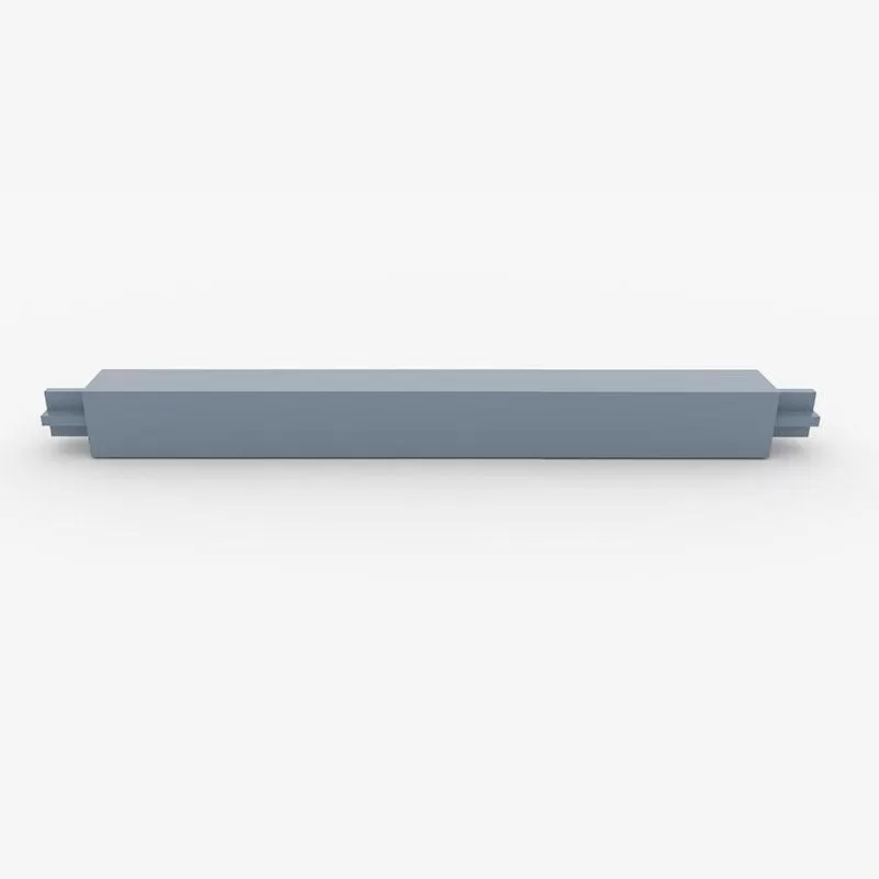
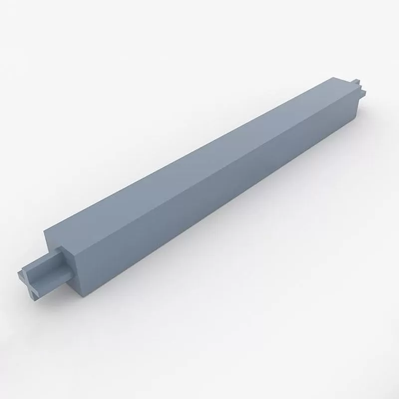
The fundamental product advantage of Buckling-Restrained Braces lies in their elegant re-engineering of a basic structural element to solve a historic weakness. Unlike conventional steel braces, which exhibit unpredictable and brittle buckling failure under compressive loads during seismic events, a BRB system decouples the axial yield function from the global buckling restraint. Its core innovation is a multi-component assembly: a ductile steel core, designed to carry axial forces, is meticulously encased within a restraining system, typically a steel tube filled with concrete or mortar. This casing is precisely debonded from the core to prevent shear stress transfer. The result is a paradigm shift in behavior: the steel core can now yield in both tension and stable, predictable compression, transforming the brace from a potential point of failure into a reliable, high-capacity energy dissipation device.

The technical superiority of this design manifests in several critical, interconnected performance advantages. First and foremost is the achievement of a full, symmetrical, and stable hysteretic response. BRBs demonstrate nearly identical strength in tension and compression, producing fat, rounded hysteresis loops that signify massive, repeatable energy dissipation without significant strength or stiffness degradation. This predictable plasticity allows engineers to employ them as designated structural "fuses" within a moment frame. In a major earthquake, the BRBs are intended to yield first, concentrating inelastic activity and damage within themselves, thereby protecting the primary gravity-load carrying system. This not only safeguards the structural skeleton but also provides a clear, inspectable, and replaceable damage path, dramatically simplifying post-event assessment and repair. Furthermore, by eliminating global buckling, BRBs utilize material with far greater efficiency. They allow for the use of smaller, more compact steel sections compared to conventional braces sized for buckling, leading to more efficient structural designs, material savings, and expanded architectural possibilities, particularly in retrofit projects.

Beyond laboratory performance, the true measure of the technology's value is the profound trust it has earned in the global engineering and construction marketplace. This trust is built on a foundation of third-party validation and rigorous standardization. Leading BRB systems are protected by invention patents in major economies, and their qualification testing—involving full-scale, proof-of-concept cyclic tests—often exceeds the demanding protocols of codes like AISC 341. This technical legitimacy has translated into widespread commercial adoption. Proven systems have been installed in over 150 buildings and critical infrastructure projects worldwide, with cumulative production exceeding tens of thousands of units. Their specification for mission-critical facilities—such as hospitals, emergency response centers, semiconductor fabrication plants, and corporate headquarters—is a powerful testament to the perceived reliability and risk-mitigation value they offer owners. Trust is further institutionalized through a mature commercial ecosystem, including technology transfer to licensed fabricators, the development of cloud-based proprietary design software for engineers, and stringent factory production control with random product testing.

In essence, BRBs represent a mature innovation where decisive technical advantages—predictable yielding, superior energy dissipation, and design efficiency—have been conclusively validated by the market. They offer engineers a reliable tool for performance-based design and provide owners with a demonstrable strategy for enhancing structural resilience, protecting assets, and ensuring business continuity in the face of seismic uncertainty.


Buckling-Restrained Brace (BRB) installation capitalizes on precise pre-fabrication and innovative designs to transform a complex seismic component into a relatively straightforward construction element, backed by robust technical ecosystems.

🏗️ Manufacturing & Site Preparation: The Foundation for Installation

A BRB's reliability is established long before it arrives on-site through stringent manufacturing and meticulous planning.

Design & Fabrication Precision: BRBs are entirely fabricated in controlled factory environments. This allows for extremely precise machining of connections and ensures the integrity of the complex core-and-restraint system. Factory production also facilitates rigorous quality control and full-scale prototype testing that often exceeds code requirements (like AISC 341), guaranteeing performance before shipment.

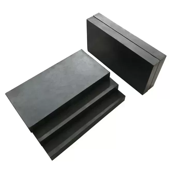
Innovative Product Design for Ease of Use: Recent innovations directly address logistical challenges. For retrofit projects in confined spaces, BRBs are now available in a two-piece, field-splice design. This allows the brace to be brought through narrow openings and assembled in place, overcoming a major limitation of traditional one-piece braces. Furthermore, all-steel BRB designs (e.g., using multiple steel tubes) eliminate the need for concrete casting and curing, significantly reducing fabrication time and producing a lighter, easier-to-handle component.

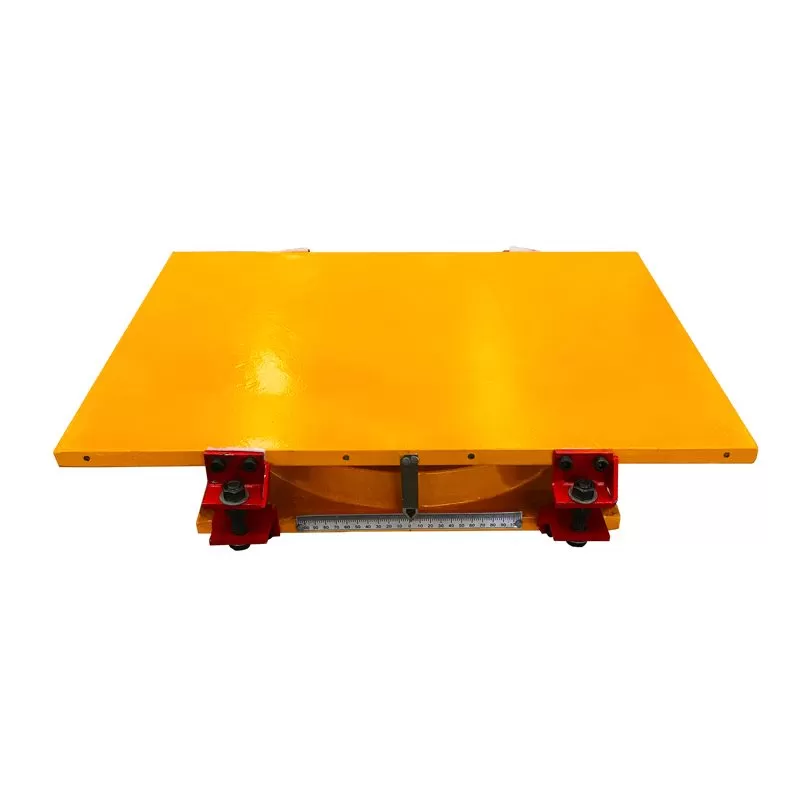
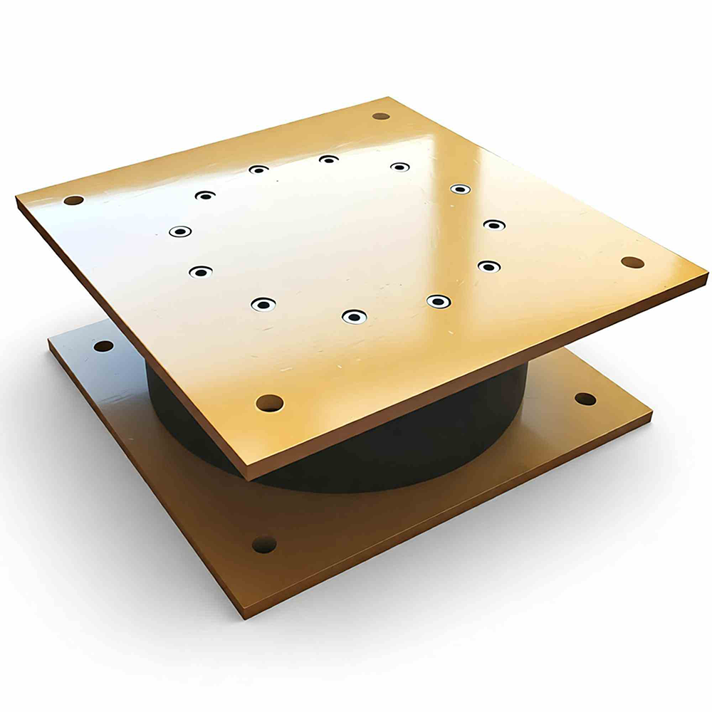
Connection and Embedded Part Engineering: The interface with the main structure is critical. Patent designs for combined-type embedded parts feature adjustable elements (like screws and limiting thread sleeves) that allow for precise positioning and fixing before concrete pouring. This solves the common problem of difficult reinforcement binding and error-prone placement, making construction "convenient" and improving efficiency.

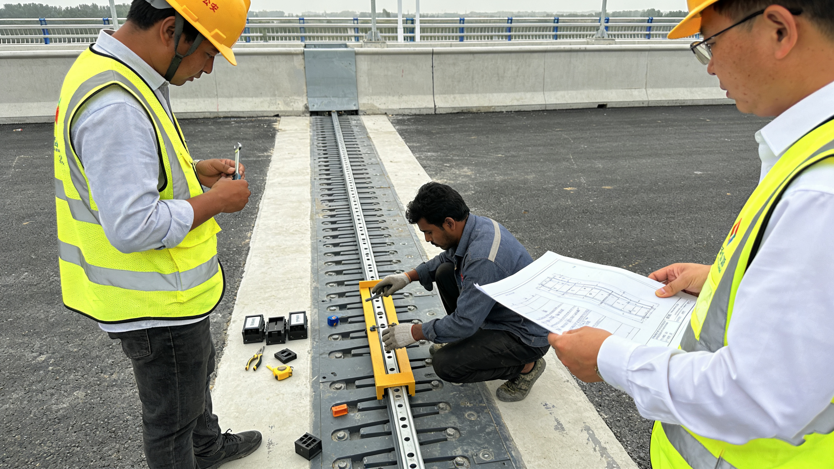
🛠️ On-Site Installation & Construction Methodology

The on-site process emphasizes precision fitting and safety, with procedures designed to manage real-world tolerances.

Pre-Installation Verification: Before hoisting, the connecting nodes on the existing beams and columns must be inspected for planar and elevation deviations. Corrections, such as flame straightening or adding base plates, are applied if offsets exceed tolerances (typically one-third of the node plate thickness).

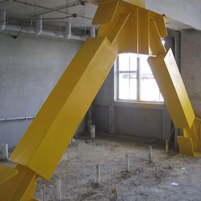
Hoisting and Temporary Placement: BRBs are hoisted using dedicated lifting lugs welded onto the restraint member. For safety and control, they are often lifted in an inclined position using two chain hoists—one pulling the upper end and one the lower—and placed onto temporary supports near their final position.

Fitting and Connection: This is the most critical phase. The actual distance between nodes is meticulously checked against the BRB's manufactured length. Minor negative errors (brace slightly too long) can be corrected by grinding down connection plates; minor positive errors (brace slightly short) can be resolved by adding weld metal. For significant errors, shim plates or node plate replacement may be necessary. The final connection to the structure is typically made using either high-strength bolting or welding, chosen based on design and seismic requirements.

⚙️ The Technical Support Ecosystem

Successful implementation relies on comprehensive support from manufacturers and researchers.

Comprehensive Engineering Support: Leading suppliers and academic teams do not just sell products; they provide integrated solutions. This includes assistance with connection design, development of proprietary cloud-based design tools for engineers, and on-site technical consultation during critical installation phases.

Technology Transfer and Training: To ensure quality and local capacity, core BRB technologies are often transferred to licensed steel fabricators through formal programs. This creates a network of qualified fabricators and erectors who are trained in the specific procedures, ensuring consistent application globally.

Active Research & Development: The field is driven by continuous R&D focused on solving construction challenges. This includes developing lighter braces, faster connection methods (like bolted options to avoid complex field welds), and application-specific solutions for bridges or near-fault zones, ensuring the technology evolves to be more constructible and economical.

In conclusion, the installation efficiency of BRBs stems from a philosophy of shifting complexity from the construction site to the controlled factory and design office. This is enabled by purpose-engineered products for difficult scenarios, precise installation protocols to manage tolerances, and a strong professional support network that ensures performance from design through to final commissioning.

For a project in the planning phase, the most impactful considerations are the type of structure (new build vs. retrofit) and the desired connection method (bolted vs. welded), as these factors dictate which product innovations and installation sequences will be most relevant and beneficial. If you have a specific project type in mind, I can provide more targeted details.


Bearing TypeStructural FeaturesCore AdvantagesApplication Scenarios
Elastomeric Bridge BearingRubber elastomer + steel plate sandwich structureLow cost, easy installationMedium and small-span highway/municipal bridges (conventional load + small deformation)
Pot BearingSteel pot + rubber plate + sealed structureHigh load-bearing capacity, strong adaptability to large displacementLong-span highway/railway bridges (heavy load + unidirectional large displacement)
Spherical Bridge BearingSpherical contact + multi-directional rotation structureMulti-directional large-angle rotation, high load-bearing capacityComplex bridge types such as cable-stayed bridges/arch bridges (complex deformation + heavy load)
LRB Isolator (Lead Rubber Bearing)Rubber body + lead core energy-dissipating componentCombines load-bearing and seismic energy-dissipating capabilitiesBridges in medium-seismic-intensity areas (load-bearing + basic seismic resistance)
HDRB Isolator (High Damping Rubber Bearing)High damping rubber material + elastic structureLead-free and environmentally friendly, high energy-dissipating efficiencyMunicipal bridges/buildings with high environmental protection requirements (seismic resistance in medium-seismic-intensity areas)
Friction Pendulum BearingSpherical sliding + pendulum-type isolation structureLarge-displacement isolation, high disaster resistanceLarge bridges in high-seismic-intensity areas (large-displacement isolation under strong earthquakes)


Application Scenarios

Highway Bridge

Highway Bridges

Ideal for highway overpasses and interchange bridges with moderate spans and loads.

Railway Bridge

Railway Bridges

Suitable for railway viaducts requiring vibration isolation and load distribution.

Urban Viaduct

Urban Viaducts

Perfect for elevated roads and urban transit systems in city environments.

Pedestrian Bridge

Pedestrian Bridges

Cost-effective solution for footbridges and light-duty crossing structures.

Technical Documents

Product Datasheet

Complete specifications and dimensions

PDF • 2.4 MB
Download

Installation Guide

Step-by-step installation instructions

PDF • 3.1 MB
Download

CAD Drawings

AutoCAD DWG files for design integration

DWG • 1.8 MB
Download

Test Certificates

Quality and performance test reports

PDF • 1.5 MB
Download

Related Products

Explore more bridge bearing solutions

Need Custom Specifications?

Our engineering team can design bearings tailored to your project requirements