Spherical Bearing - Key Product Advantages
The selection of spherical bearings represents a strategic engineering decision that delivers significant advantages beyond basic specifications. Our spherical bearing solution is engineered to provide unmatched performance, reliability, and value throughout the entire project lifecycle—from design through decades of service.
I. Core Technical Superiority: Engineered for Extreme Performance
1. Unmatched Load-Rotation Synergy
Our spherical bearings uniquely deliver simultaneous high-load capacity and multi-directional rotation, a critical combination where other bearing types force compromises.
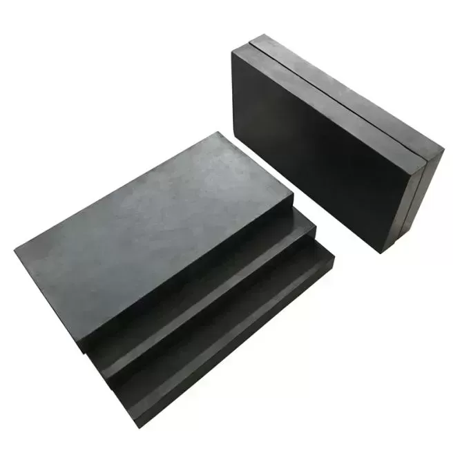
Extreme Load Capacity: Engineered for vertical loads from 2,000 kN to over 600,000 kN, positioning them as the world's premier choice for mega-projects like record-span cable-stayed, suspension bridges, and offshore heavy-duty structures. They ensure the absolute stability of the most critical structural nodes under the planet's most demanding loads.
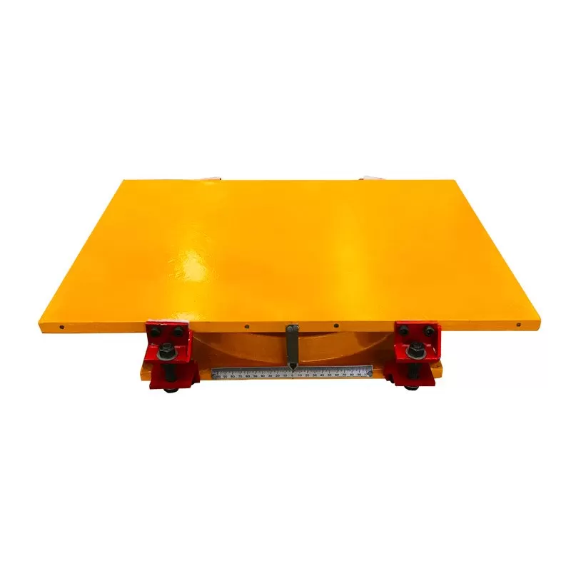
True Multi-Directional Rotation: Unlike single-axis bearings, our spherical design accommodates large-angle rotation (±0.5° to ±3.5°) in any horizontal direction from a single pivot point. This is essential for accommodating complex, unpredictable movements in curved bridges, seismic zones, and structures with compound deformation.
2. Friction-Optimized, Wear-Free Movement
The precision-machined spherical steel-on-polymer interface (using PTFE, UHMWPE, or advanced UHPF) provides extremely low and consistent friction (μ as low as 0.5-1.5% dynamic). This translates to:
Minimal horizontal forces transferred to piers and abutments.
Predictable force distribution for more accurate structural modeling.
A wear-free rotational core that requires no maintenance, unlike mechanisms with sliding or rolling parts.
II. Long-Term Value & Risk Mitigation
3. Century-Long Durability & Corrosion Defense
Built for a 100+ year design life, our bearings are engineered for longevity.
Advanced Material Science: The use of high-performance polymers (UHPF) and forged alloy steels provides exceptional resistance to wear, creep, and environmental degradation.
Comprehensive Corrosion Protection: Featuring hot-dip galvanizing (ISO 1461) or high-specification coating systems tailored to the project's environmental class (C4-C5), they withstand harsh marine, industrial, and extreme weather conditions.
Sealed for Life: Multi-layer sealing systems protect the critical spherical interface from contaminants like water, dust, and de-icing salts.
4. Universal Compliance & Independent Validation
Trust is built on verification and global certification. We provide full compliance with major international and regional standards:
Primary Design Standards: EN 1337-7 (Europe), AASHTO LRFD (USA)
Key Regional Standards: BS 5400 (UK), AS 5100.4 (Australia), IRC 83 (India), GOST 15150 (Russia/CIS region)
Comprehensive Third-Party Testing Reports from accredited laboratories, validating load capacity, rotation, friction, and fatigue performance.
Full Material Traceability with mill certificates for all critical components.
Detailed Design Calculation Reports that provide complete transparency into the engineering, ensuring the bearing is perfectly matched to your project's specific loads and movements.
III. Project-Specific Flexibility & Global Support
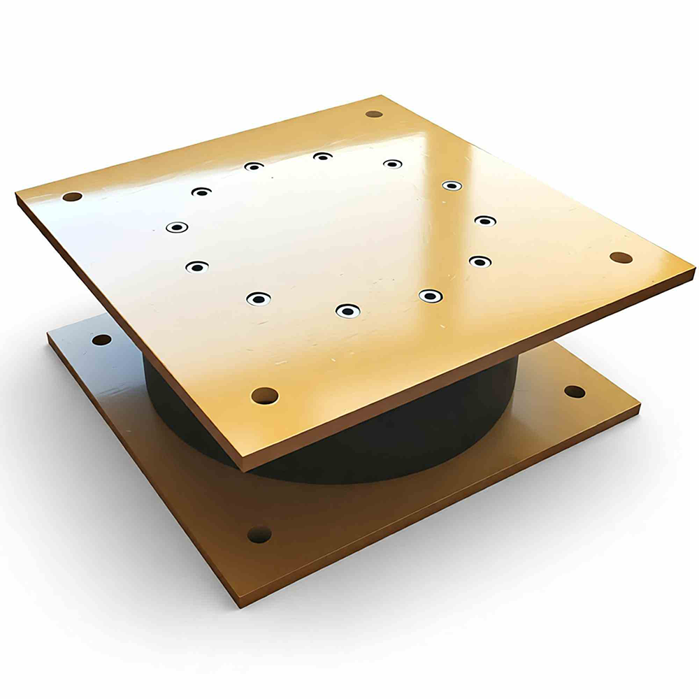
5. Complete, Full-Dimensional Customization
We provide engineered-to-order solutions, not just catalog products.
Tailored Geometry: Customization of diameter, height, spherical radius, and mounting configuration to fit precise spatial and load requirements.
Material Optimization: Selection of the optimal sliding material (PTFE, UHMWPE, or UHPF) and steel grades based on pressure, environment, and lifecycle cost goals.
Application-Specific Design: Bearings are configured as fixed, guided, or free-sliding and can be integrated with seismic dampers, load cells, or monitoring systems.
6. Global Logistics & Project Integrity
We ensure our products arrive on site in perfect condition, anywhere in the world.
Export-Grade Protective Packaging: Utilizing heavy-duty, weather-resistant crating designed for long-distance sea and land transport, preventing damage from handling and environmental exposure.
Turnkey Logistics Support: Management of complex shipping, customs clearance, and delivery to remote project sites.
On-Site Technical Assistance: Available installation supervision and commissioning support to ensure perfect implementation according to specifications.
Competitive Differentiation & Client Value Summary
Choosing our spherical bearings is an investment in predictable project outcomes and long-term structural integrity. The advantages translate directly into:
Reduced Total Cost of Ownership: Minimal maintenance and a 100-year service life lower lifecycle costs significantly.
Decreased Project Risk: Independent validation, proven durability, and expert support mitigate technical and scheduling risks.
Enhanced Design Freedom: The ability to handle complex, multi-directional movements enables more innovative and efficient bridge designs.
Uncompromised Safety & Compliance: Full adherence to global standards (EN, AASHTO, BS, AS, IRC, GOST) ensures regulatory acceptance and public safety.
In essence, our spherical bearing solution combines technical excellence, verifiable quality, and seamless project integration to deliver not just a component, but a cornerstone of reliability for your most ambitious structures.
Spherical Bearing - Installation & Construction Guide
The successful performance of a spherical bearing hinges on its correct integration with the superstructure. Recognizing that installation methods differ fundamentally between prefabricated, cast-in-place, and steel girders, this guide outlines tailored procedures for each. Our bearings are engineered with a self-aligning spherical core that inherently accommodates real-world construction tolerances and simplifies the installation process across all project types.
Pre-Installation Foundation: Universal Preparations
Regardless of the superstructure type, the following prerequisites ensure a successful start:
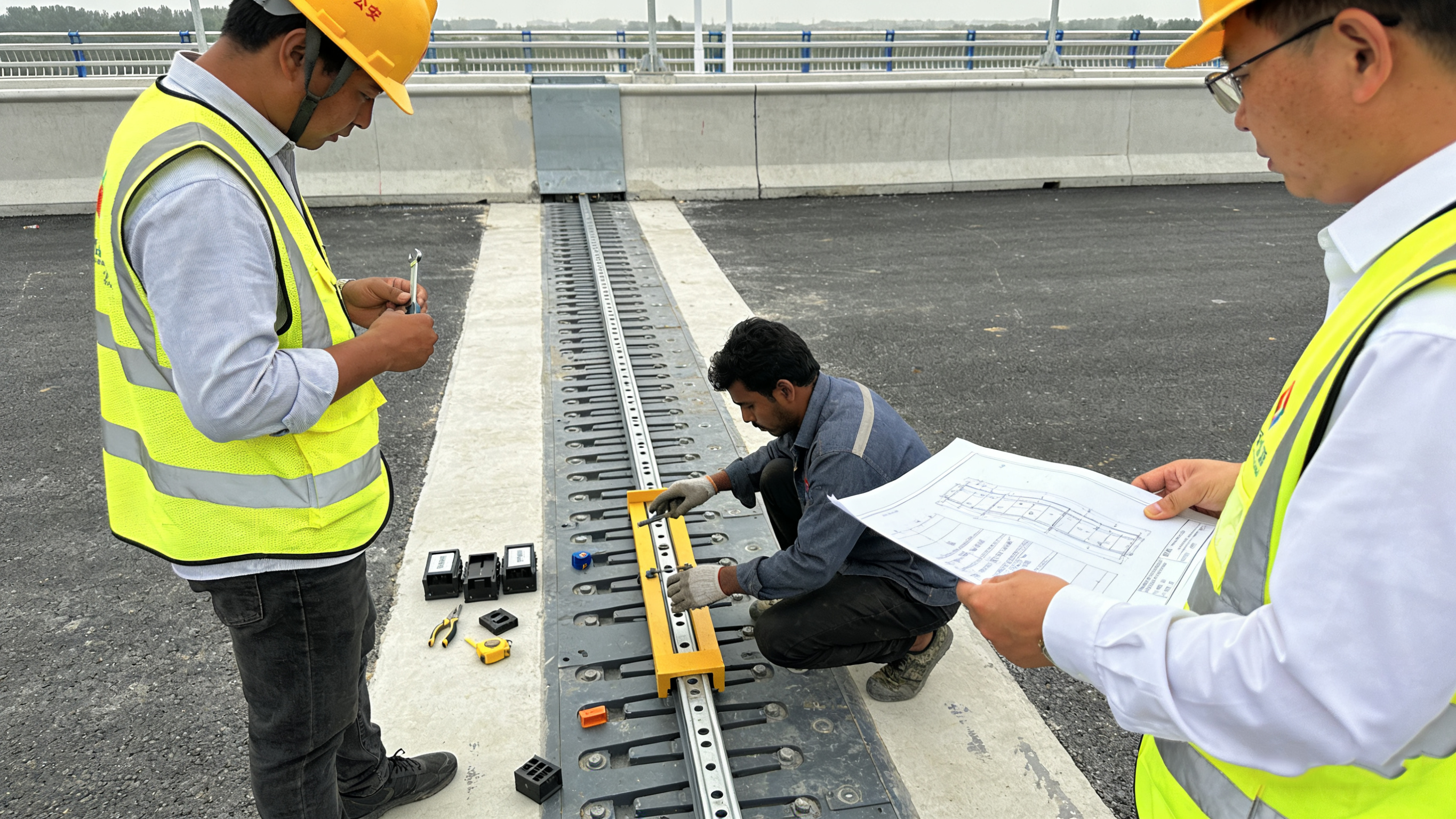
Documentation Review: Thoroughly examine the supplied Installation Dossier, including shop drawings, bolt torque specifications, and the project-specific method statement.
Support Preparation: The bearing pedestal or sole plate must be constructed to the specified elevation, levelness (typically within a 1:200 gradient), and plan location (tolerance ±5 mm).
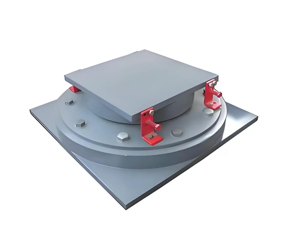
Bearing Inspection & Handling: Upon receipt, inspect the bearing for any transit damage. Lift the unit only via its designated lifting lugs or holes using soft slings to protect the finish.
Tailored Installation Procedures by Superstructure Type
A. For PRECAST CONCRETE GIRDERS
Characteristics: The bearing receives the full dead load of the girder instantly upon placement. Precision in initial positioning is critical.
Installation Sequence:
Bearing Positioning: Place and securely fix the spherical bearing onto the pier/abutment. Confirm final plan alignment and anchor bolt torque.
Girder Placement: Carefully lower the precast girder onto the bearing. The self-aligning spherical surface will automatically rotate to match the girder’s bottom inclination, ensuring full contact.
Verification & Grouting: After the girder is seated, verify alignment. Proceed with grouting the interface between the girder bottom and the bearing’s top plate if specified. Do not restrain the bearing’s rotational freedom.
B. For CAST-IN-PLACE CONCRETE GIRDERS
Characteristics: Load is applied gradually. The bearing must be protected and may require temporary locking during construction.
Installation Sequence:
Bearing Installation with Temporary Lock: Install and fix the bearing on the support. To prevent concrete ingress and control position during pouring, install temporary locking devices or shims to restrain rotation, if provided or specified.
Formwork & Concrete Placement: Erect formwork and place reinforcing steel. Pour the concrete for the girder segment. The locked bearing acts as a stable support.
Activation: Once the concrete has gained sufficient strength and the formwork is removed, remove all temporary locks or shims. As subsequent construction phases (e.g., additional deck pours) proceed, the bearing will begin to rotate freely to accommodate deformations.
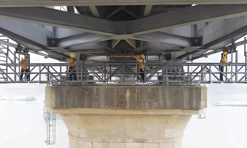
C. For STEEL GIRDERS
Characteristics: Interface is typically via direct contact or a welded/bolted sole plate. Alignment and interface treatment are key.
Installation Sequence:
Interface Preparation: Ensure the bearing’s top surface and the underside of the steel girder or its attached sole plate are clean, dry, and free of paint or debris at the contact area.
Bearing Placement: Fix the bearing onto the substructure.
Girder Erection & Connection: Lower the steel girder onto the bearing. For direct contact, the spherical surface will self-align. For bolted connections, align the holes and insert bolts, tightening to the specified torque. For welded connections, complete the specified welds between the girder’s sole plate and the bearing’s top plate, following controlled welding procedures to minimize heat distortion.
Freedom of Movement Check: After final connection, ensure any guide bars or shear blocks have the specified clearance and that the sliding surfaces (if applicable) are free to move.
Universal Advantages for Simplified Construction
Across all girder types, our spherical bearings provide inherent benefits that reduce complexity and risk:
Self-Alignment: The spherical design automatically compensates for minor angular misalignments between the substructure and superstructure, eliminating the need for precise shimming.
Tolerance Accommodation: The system is designed to accommodate typical construction tolerances in plan position, elevation, and angular alignment without compromising performance.
Pre-Assembled Reliability: Supplied as a single, sealed unit, eliminating on-site assembly errors related to internal components.
Clear Visual Guidance: Permanent markings indicate centerlines, lift points, and sliding direction, preventing orientation mistakes.
Post-Installation & Quality Assurance
Upon completion of installation for any girder type, a final verification must be conducted:
Confirm removal of all transportation restraints, temporary locks, or packaging.
Verify that anchor bolts are torqued to the specified value.
Visually inspect for full contact and ensure no obstructions inhibit the intended movement (rotation or slide).
Document the “as-built” position and condition.
Conclusion: Our spherical bearing system is engineered to integrate seamlessly into diverse construction methodologies. By providing a robust, self-compensating interface between substructure and superstructure—whether concrete or steel, precast or cast-in-place—it delivers predictable performance through a simplified, reliable installation process, forming a solid foundation for the lifetime of the structure.