Key Advantages of Our Pot Bearings
We deliver pot bearings that combine definitive engineering performance with complete project-ready support, providing unmatched reliability and value.
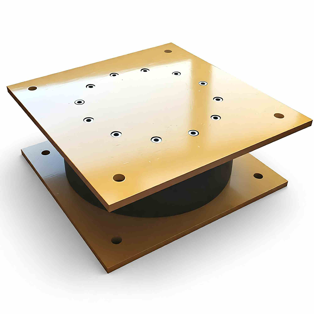
1. Engineered for Unmatched Performance & Reliability
Extreme Load Capacity & Distribution: Supports 1,000 to over 200,000 kN, reliably bearing immense loads while distributing them evenly to minimize structural stress.
Controlled Movement Accommodation: Precisely accommodates horizontal displacement (±600mm) and defined rotation to handle thermal expansion, creep, and settlement.
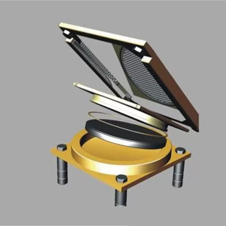
Durable, Maintenance-Free Operation: The sealed, pressure-confined elastomeric disc and robust construction ensure long-term performance with minimal lifecycle cost.
2. Full Compliance, Certification & Documentation
Independently Verified Performance: Backed by accredited third-party test reports and CE Marking (EN 1337-5), with compliance for AASHTO, AS, IRC and other global standards.
Complete Technical Dossier: Includes a detailed Project Calculation Report for engineering approval and validation.
Streamlined Logistics Support: We provide a full suite of export and technical documents (commercial invoices, packing lists, certificates, manuals), simplifying customs clearance and project administration.
3. Complete Customization & Project Integration
Total Design Flexibility: Fully customizable for load, dimensions, rotation limits, sliding materials (PTFE/UHMWPE), and connections to meet exact specifications.
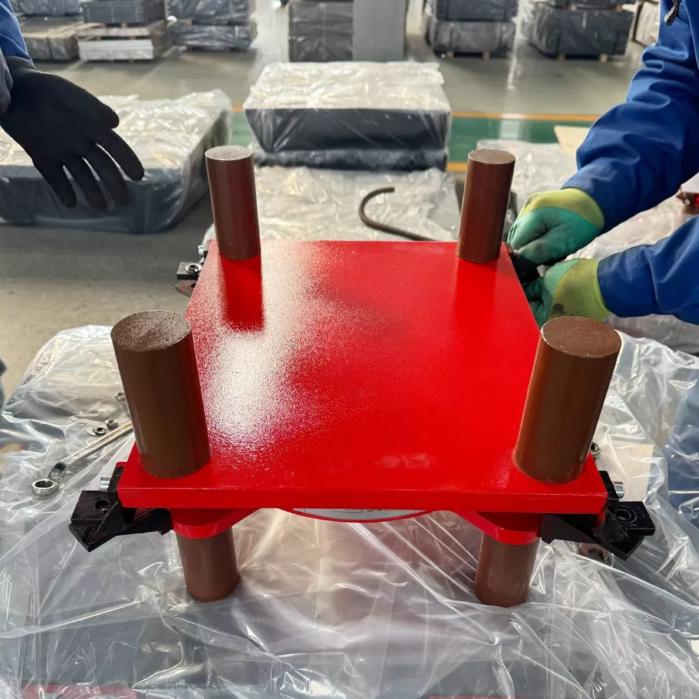
Secure Global Delivery: Each unit is shipped in robust, export-ready wooden crating, ensuring secure arrival worldwide.
4. Distinct Value for Every Partner
For Distributors: A high-margin, technically certified product with reliable 15-35 day lead times and full sales support.
For Engineers: Guaranteed performance, risk-mitigated compliance, and seamless integration, ensuring project safety and schedule certainty.
Engineered for Certainty. Delivered with Complete Support.
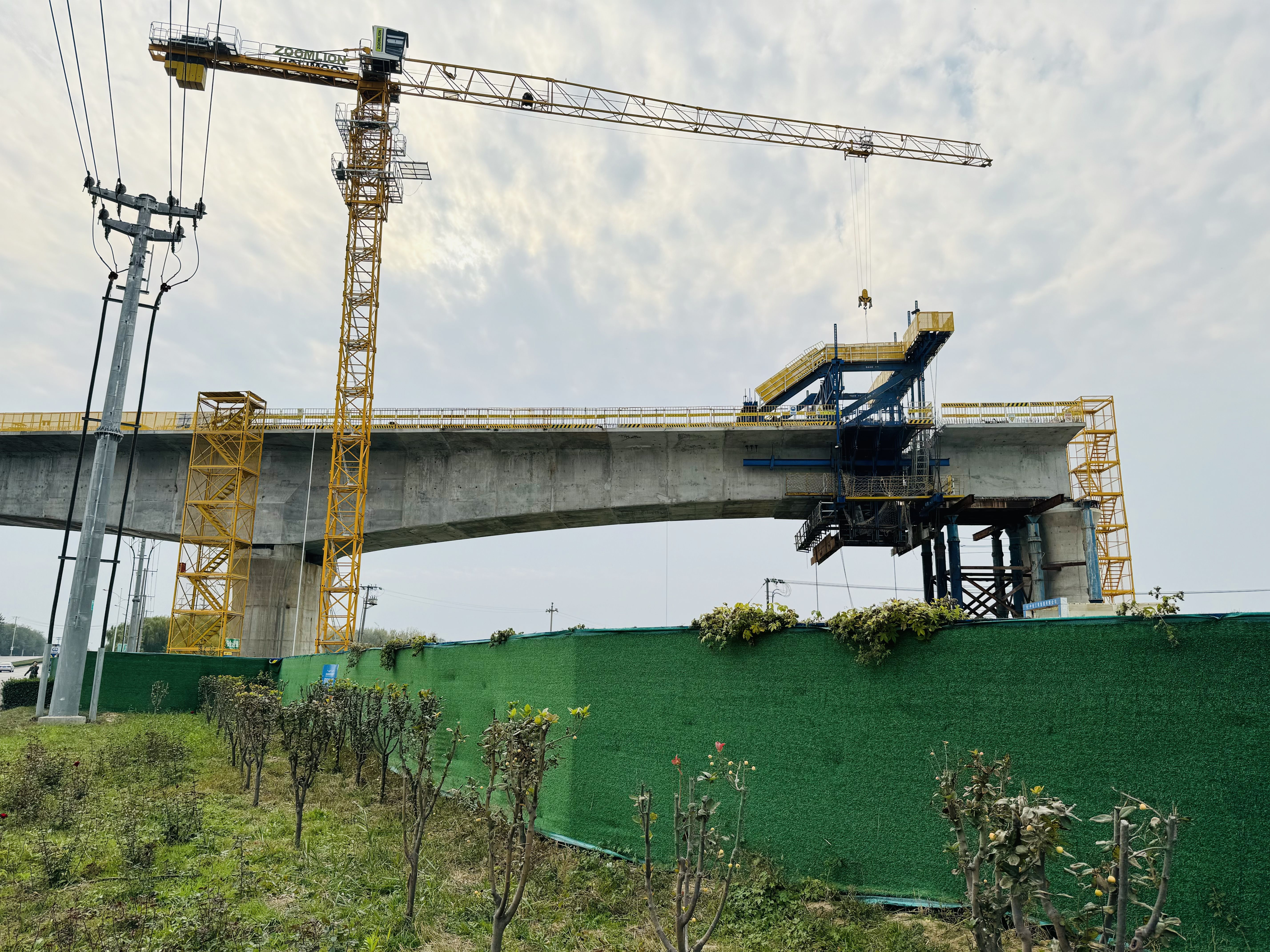
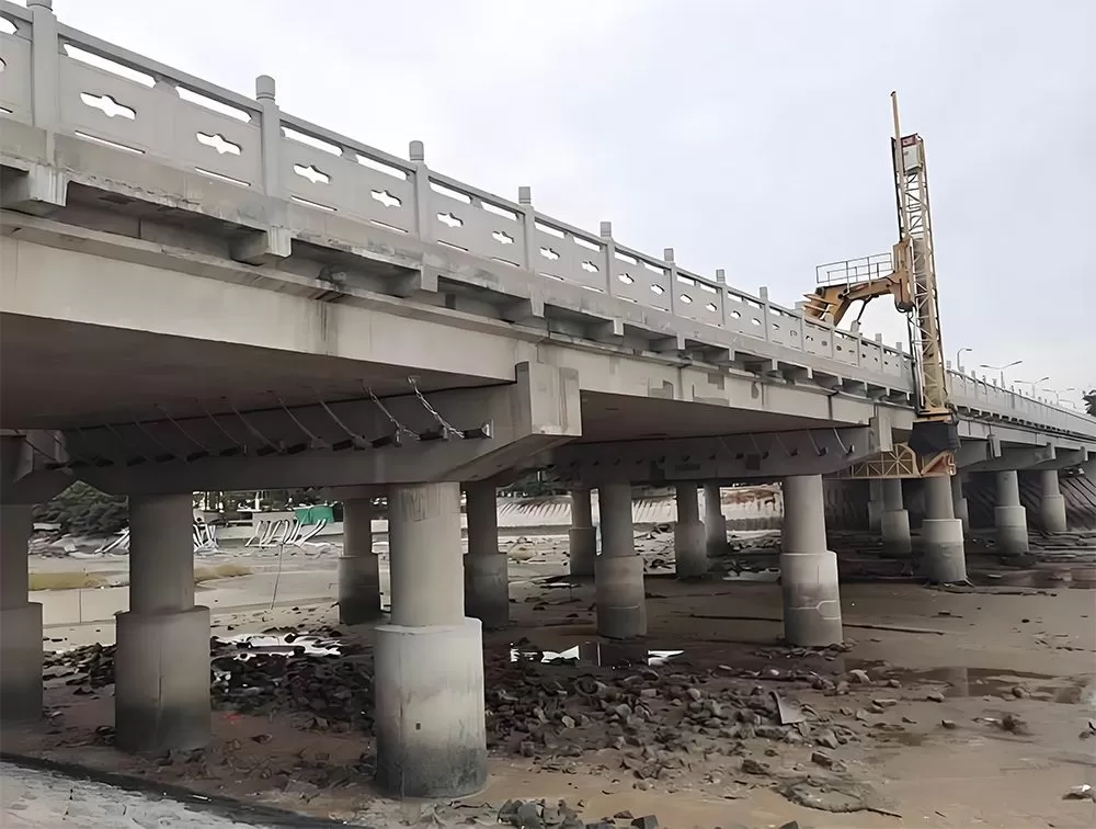
Installation & Construction: Tailored Procedures for Different Superstructures
The installation of pot bearings varies significantly depending on the type of superstructure they support. Our guidance is tailored to ensure correct and efficient installation for each specific application, maximizing performance and longevity.
Core Principle: Built-in Site Adaptability
All our pot bearing designs accommodate typical on-site variations with a positional adjustment tolerance of ±5 to ±10 mm. This built-in flexibility helps mitigate minor construction deviations without compromising performance.
Installation for Cast-in-Place Concrete Beams/Girders
This method involves securing the bearing before the concrete pour, integrating it into the monolithic structure.
Preparation & Positioning:
After constructing the substructure (pier/abutment cap), precisely position and temporarily fix the pot bearing onto it using the embedded anchor bolts or a temporary frame.
Ensure perfect leveling and alignment per shop drawings before proceeding.
Integration with Formwork & Reinforcement:
Erect the beam soffit formwork around the bearing. The bearing's top plate often acts as part of the formwork.
Carefully place the reinforcement cage, ensuring it clears the bearing's top connector plates or shear keys.
Concrete Placement & Curing:
Pour concrete, taking care not to displace the bearing. Vibrate concrete thoroughly around the bearing to ensure full encapsulation and no voids.
Allow the concrete to cure properly. The bearing becomes permanently encased and fixed upon curing.
Key Consideration: The bearing must be impeccably positioned and locked before the pour, as adjustments afterward are impossible.
Installation for Precast Concrete Beams/Girders
Here, the bearing is installed on the substructure, and the precast element is then lowered onto it.
Substructure Preparation & Bearing Fixing:
On the completed substructure, position the pot bearing. For fixed types, grout the base plate cavity with high-strength non-shrink grout.
For sliding types, prepare and align the stainless steel sliding plate.
Beam Erection & Placement:
The precast beam, with pre-prepared mating surfaces (e.g., grout pockets or sole plates), is lifted and carefully lowered onto the bearing.
Use the built-in tolerance to make final horizontal adjustments for perfect alignment with other beams.
Final Connection:
For grouted connections, fill the interface between the beam and the bearing's top plate with high-strength grout.
For bolted connections, insert and torque the connecting bolts.
Key Consideration: Coordination between bearing installation height and the precast beam's underside elevation is critical.
Installation for Steel Beams/Girders
This typically involves direct bolted connections, offering high precision and adjustability.
Bearing Installation on Substructure:
Fix the pot bearing to the concrete substructure via anchor bolts grouted into the cap or using a base plate leveled with shim packs and grouted.
Beam Lowering & Alignment:
The steel beam, with pre-drilled holes in its bottom flange or attached sole plate, is lowered onto the bearing.
Temporary bolts or pins are used to hold it in place while final alignment checks are made.
Permanent Bolted Connection:
Insert high-strength friction-grip bolts through the mating holes in the beam and the bearing's top plate.
Tighten all bolts to the specified pre-tension (torque) in the correct sequence to ensure a rigid, slip-critical connection.
Key Consideration: Strict adherence to bolt tightening procedures is essential to achieve the required clamping force and connection stiffness.
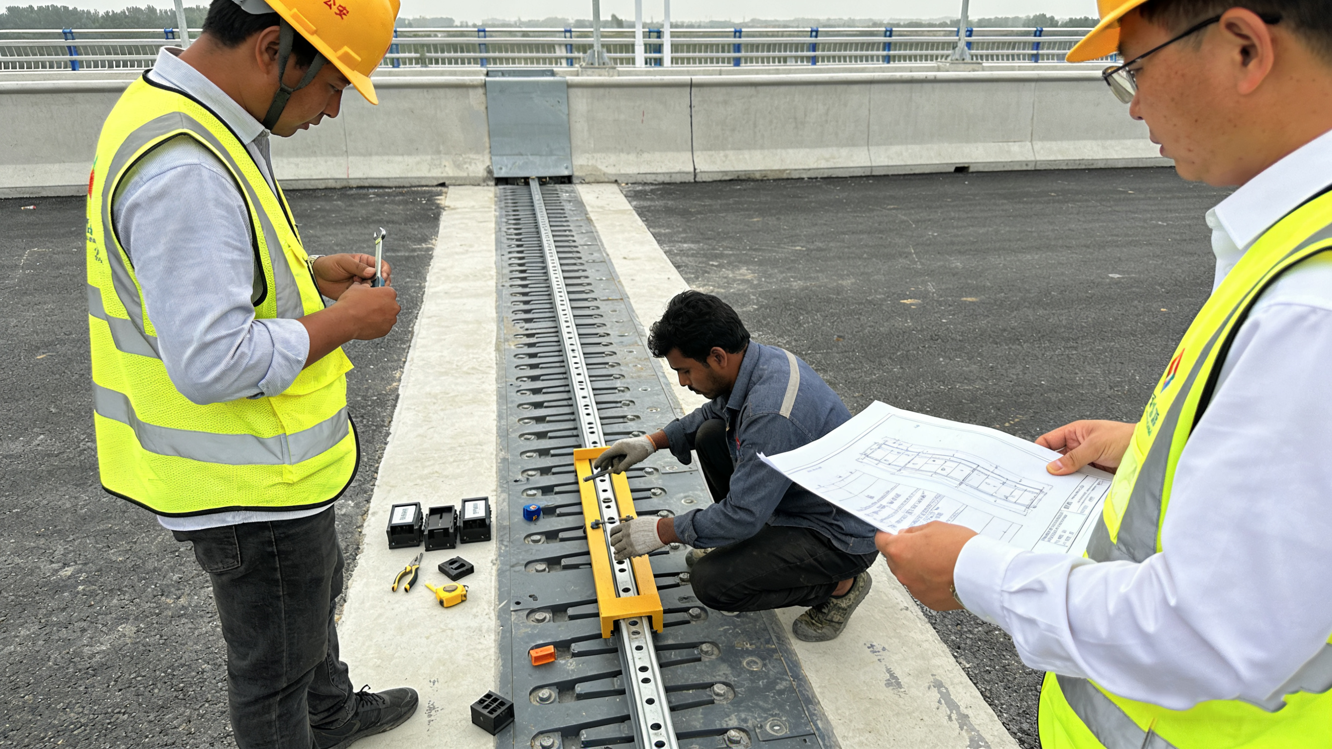
Universal Final Verification (All Types)
Regardless of the superstructure type, a final check is mandatory:
Verify final position, level, and alignment.
Confirm unobstructed movement capability for sliding/guided types.
Ensure all bolts are torqued or all grout has cured.
Your Technical Support Package
We ensure successful installation through:
Structure-Specific Installation Drawings: Detailed plans for your exact beam type and bearing model.
Comprehensive Method Statements: Step-by-step guides tailored to cast-in-place, precast, or steel construction.
Real-Time Technical Support: Direct access to our engineers for clarification during critical installation phases.
Download the specific guide for your project type or contact us for tailored drawings.
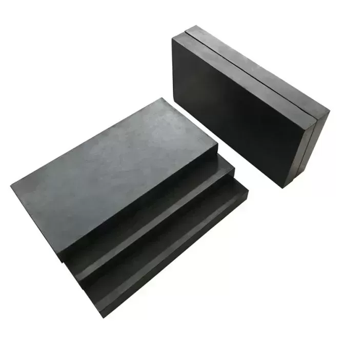
From a structural perspective: Pot bearings utilize a pot-shaped sealing structure, making them more suitable for long-term stability requirements under complex working conditions; while disc bearings primarily use a disc-shaped structure, focusing on lightweight installation scenarios.
In terms of load-bearing capacity: Pot bearings are suitable for high-load scenarios and can meet the heavy-load requirements of large-span bridges; disc bearings are more suitable for medium-to-low load scenarios and are mostly used in small and medium-span structures.
Regarding rotational angle capability: Pot bearings support larger rotational angles, making them suitable for bridge types with large beam deformations; the rotational angle range of disc bearings is relatively limited, making them more suitable for conventional deformation scenarios.
In terms of applicable bridge types: Pot bearings are commonly used in large-span highway bridges, railway bridges, and urban elevated bridges; disc bearings are mostly used in small and medium-span municipal bridges, pedestrian bridges, and other lightweight structures.
In terms of customization flexibility: Pot bearings support full-dimensional structural and parameter customization, allowing them to match specific project requirements; the customization dimensions of disc bearings are relatively concentrated on basic specification adjustments.
.webp)
.webp)