Products

LRB Isolator

Superior Seismic Performance for Protecting Critical Infrastructure and Life Safety

As the definitive passive seismic isolation solution, our Lead Rubber Bearing (LRB) Isolator integrates a high-damping lead core within a multi-layer elastomeric system. It provides unparalleled energy dissipation, accommodates large displacements while maintaining stable vertical support, and ensures long-term reliability for bridges, critical buildings (hospitals, schools, data centers), and strategic assets like LNG terminals and nuclear facilities in high-seismic regions.

WhatsApp: +86 19932366878
Email: info@kingwork.com

Lead Rubber Bearing (LRB) Isolator - Product Overview

Defining Seismic Resilience Through Engineered Isolation

The Lead Rubber Bearing (LRB) Isolator represents the pinnacle of passive seismic protection technology. It is not merely a structural component but an integrated energy-dissipation system engineered to fundamentally alter how a structure responds to earthquake forces. By strategically decoupling the superstructure from the damaging horizontal motions of the ground, the LRB drastically reduces seismic demand, transforming potential catastrophic failure into manageable, controlled movement. Its core innovation—a solid lead plug encased within a precisely engineered laminated rubber-steel bearing—provides both the flexibility for displacement and the definitive hysteretic damping to absorb seismic energy.

Core Value Proposition & Product Positioning

Positioned as the preferred and most reliable solution for base isolation, the LRB Isolator serves a critical market segment: projects where life safety, functionality continuity, and asset protection are paramount. It occupies a unique space between simple, low-damping elastomeric isolators and more complex active damping systems, offering an optimal balance of proven performance, robust durability, and cost-effectiveness over the structure's lifecycle. We position it as the definitive choice for engineers and owners who seek to achieve resilience by design, providing quantifiable risk reduction for critical infrastructure.

Mechanism of Action: The Synergy of Flexibility and Damping

The LRB's exceptional performance stems from the synergistic combination of its two primary elements:

Laminated Rubber & Steel Plates: Provides high vertical stiffness to support gravity loads while offering low horizontal stiffness. This allows the isolator to accommodate large lateral displacements (often exceeding 300-400% shear strain) with stability.

Central Lead Core: The key differentiator. The lead core yields plastically at low force levels, providing immediate, reliable, and substantial hysteretic damping. This damping is velocity-independent and stable across cycles, effectively converting destructive seismic kinetic energy into heat, thereby reducing the forces transmitted to the structure by up to 70-80% compared to fixed-base conditions.

Prime Applications: Protecting What Matters Most

LRB Isolators are the specified solution across a spectrum of critical and high-value infrastructure:

Critical Buildings & Lifeline Facilities:

Hospitals & Emergency Response Centers: Ensures operational continuity post-earthquake.

Schools, Universities, and Public Assembly Buildings: Protects large occupancies and provides safe egress.

Data Centers & Telecommunications Hubs: Safeguards vital digital infrastructure and prevents catastrophic data loss.

Retrofit of Historic or Vulnerable Existing Structures: Enhances seismic performance without compromising architectural integrity.

Essential Transportation & Civil Infrastructure:

Highway & Railway Bridges: Isolates the deck from pier motions, protecting substructures and ensuring route availability for emergency response.

Airport Control Towers & Terminals: Maintains functionality of critical transportation nodes.

High-Hazard Industrial & Energy Assets:

LNG Terminals, Petrochemical Plants: Prevents catastrophic failures that could lead to fires, explosions, or environmental disasters.

Nuclear Power Facilities (Non-Nuclear Safety-Related): Protects ancillary buildings and structures, mitigating risk of secondary hazards.

Power Generation & Substation Buildings: Ensures the continuity of energy supply networks.

Summary: The Investment in Predictable Performance

Choosing the LRB Isolator is an investment in quantifiable safety and resilience. It delivers a robust, maintenance-free isolation solution with predictable and verifiable dynamic properties. By allowing engineers to design for significantly reduced forces, it enables more efficient superstructures and provides owners with the ultimate assurance: that their asset is engineered to withstand seismic events, protecting both human life and long-term economic value.

LRB Isolator
Parameter CategorySpecificationTechnical Details & Design Notes
1. DIMENSIONAL SPECIFICATIONS

Standard Diameter Range300 mm - 2000+ mmTypical Project Range: 400 mm - 1200 mm Large Projects: Up to 2000+ mm for heavy structures Custom Sizes: Available outside standard range based on project requirements Bridge Applications: Typically 500-1500 mm Building Applications: Typically 300-800 mm
Total Rubber Thickness (Tr)50 mm - 400+ mm Typically 20-35% of diameterDetermines the horizontal flexibility and displacement capacity Design Formula: Maximum displacement ≈ Tr × γ_max Where γ_max is the maximum shear strain (typically 200-300%) Bridge Applications: Thicker for larger displacements Building Applications: Optimized for specific building drift requirements
Shape Factor (S)8 - 40 (Standard: 12-30)S = Loaded area / Force-free area Higher S = Greater vertical stiffness, better stability Critical for preventing buckling under large displacements Bridge Applications: Typically 15-30 for high stability Building Applications: Typically 12-25
Lead Core Diameter50 mm - 400+ mm Typically 15-25% of bearing diameterDirectly affects yield force and energy dissipation capacity Larger core = Higher damping, greater initial stiffness Optimized based on seismic design requirements Design Value: Based on required characteristic strength (Qd)
2. MECHANICAL & SEISMIC PERFORMANCE

Vertical Load Capacity500 kN - 40,000+ kN Pressure: 5-15 MPaService Load: 5-10 MPa typical Maximum Load: Up to 15 MPa for specific applications Vertical stiffness is high to limit static settlement Bridge Applications: Typically higher loads (10,000-40,000 kN) Building Applications: Typically moderate loads (500-20,000 kN)
Shear Modulus (G) - Application SpecificBridge Applications: 0.7 - 1.2 MPa Building Applications: 0.3 - 0.7 MPaBridge Applications (G = 0.7-1.2 MPa): • Higher stiffness for bridge dynamic requirements • Better stability under traffic and wind loads • Suitable for longer spans and heavier loads Building Applications (G = 0.3-0.7 MPa): • Lower stiffness for building isolation • Longer isolated period for better seismic performance • Suitable for medium to high-rise buildings Note: Shear modulus affects horizontal stiffness: K_h = GA/Tr
Horizontal Stiffness (Keff)0.3 - 15 kN/mm Effective stiffnessDepends on rubber properties and geometry Effective Stiffness: Varies with displacement amplitude Post-Yield Stiffness Ratio: Kd/K1 ≈ 6-12% (Where K1 is initial stiffness) Bridge Applications: Typically higher stiffness (1-15 kN/mm) Building Applications: Typically lower stiffness (0.3-5 kN/mm)
Yield Force (Qd)5% - 15% of Vertical Load Typically 8-12%Force at which lead core yields and damping begins Design Value: Qd = τy × Apb Where τy ≈ 10-11 MPa for pure lead Apb = area of lead plug Bridge Applications: Typically 8-12% of vertical load Building Applications: Typically 6-10% of vertical load
Maximum Shear Strain (γmax)200% - 350% Design: 250-300%Maximum allowable horizontal displacement relative to total rubber thickness Design Displacement: Δmax = γmax × Tr For 250% strain and Tr = 200 mm: Δmax = 500 mm Bridge Applications: Typically 250-300% (higher for seismic regions) Building Applications: Typically 200-250%
Horizontal Equivalent Damping Ratio (ξeq)15% - 30% Typically 20-25%Measures energy dissipation capacity of the isolation system Formula: ξeq = ED/(2πKeffΔ2) Where ED = energy dissipated per cycle Higher damping reduces seismic forces transmitted to structure Bridge Applications: Typically 20-25% Building Applications: Typically 15-20%
Characteristic Strength (Q)Force-based specification: 50 kN - 5000+ kNRepresents the force level at which significant energy dissipation begins Directly related to lead core properties and size Critical for determining force-displacement hysteresis loop Bridge Applications: Typically higher (500-5000+ kN) Building Applications: Typically lower (50-2000 kN)
3. MATERIAL PROPERTIES

Elastomer CompoundNatural Rubber (NR) Custom formulations availableNatural Rubber (NR) Properties: • High resilience and fatigue resistance • Excellent low-temperature performance • Long-term stability and aging resistance • Low creep under sustained loads • Comply with ASTM D2000, ISO 4637 standards Custom Formulations: Available for specific temperature ranges, chemical resistance, or special performance requirements
Lead Core99.9% Pure Lead ASTM B29 or equivalentKey Properties: • Yield stress: 10-11 MPa • Recrystallizes at room temperature (self-healing property) • Maintains consistent mechanical properties over thousands of cycles • High density provides gravitational stability • Excellent energy dissipation characteristics
Steel LaminatesMild Steel Plates 3-12 mm thicknessFunction: Constrain rubber, provide vertical stiffness, prevent bulging Material: ASTM A36, A709, S355, or equivalent Surface Treatment: Sandblasted and primed for optimal rubber bonding Bond Strength: > 7 MPa rubber-to-steel adhesion Corrosion Protection: Painted or galvanized as required
Connection PlatesTop/Bottom Steel Plates 25-60 mm thicknessMaterial: Structural steel (ASTM A572, S355) Anchor Options: Bolted, welded, or grouted connections Corrosion Protection: Hot-dip galvanizing or paint systems per ISO 12944 Bridge Applications: Typically thicker plates for higher loads Building Applications: Standard thickness based on load requirements
4. DYNAMIC PROPERTIES & TESTING

Natural Period RangeIsolated Structure: 2.0 - 4.0 secondsIsolation Effect: Lengthens structure period away from dominant earthquake periods Design Formula: T = 2π√(M/Keff) Where M is supported mass, Keff is effective horizontal stiffness Bridge Applications: Typically 2.0-3.5 seconds Building Applications: Typically 2.5-4.0 seconds
Frequency DependenceMinimal variation: 0.1 Hz - 2.0 HzLRB properties remain relatively stable across typical earthquake frequency range Strain Rate Effect: Modest increase in stiffness with velocity (10-20% increase at 500 mm/s vs 50 mm/s) Temperature Effect: Properties stable across design temperature range
Temperature RangeOperational: -30°C to +50°C Extended: -40°C to +70°CStandard Range: -30°C to +50°C Extended Range: -40°C to +70°C available with special compounds Low-Temperature Performance: Stiffness increases below 0°C High-Temperature Performance: Properties stable up to 50°C; lead melting point 327°C
Prototype Testing RequirementsPer ASCE 7, EN 15129, ISO 22762, AASHTOStandard Test Sequence: 1. Static vertical load test 2. Horizontal shear tests at multiple amplitudes (50%, 100%, 150%, 250% design displacement) 3. Stability test at maximum displacement under vertical load 4. Long-term aging and environmental tests (optional) 5. Fatigue tests for cyclic performance verification
5. DURABILITY & LIFECYCLE

Design Life25 - 50+ years Maintenance-free operationStandard Design Life: 25-50 years depending on application and environment Extended Life: 50+ years available with enhanced materials and protection No Routine Maintenance: Sealed design protects internal components Inspection: Visual inspection recommended every 5-10 years Bridge Applications: Typically 50+ years to match bridge design life Building Applications: Typically 25-50 years
Aging & Environmental ResistanceUV, Ozone, Oxidation resistant Weatherproof designProtection: External rubber layer contains antioxidants and anti-ozonants Sealing: Rubber cover protects steel plates from corrosion Lead Encapsulation: Lead core fully enclosed, no environmental exposure Chemical Resistance: Resistant to most common environmental chemicals
Seismic Event PerformanceMultiple design earthquakes Without performance degradationDesign Basis: Capable of performing through multiple design basis earthquakes (DBE) and maximum considered earthquakes (MCE) Self-healing Lead Core: Lead recrystallizes at room temperature, restoring properties after yielding Fatigue Resistance: Designed for thousands of cycles without degradation Post-Earthquake Inspection: Minimal inspection required after seismic events
6. DESIGN CODES & COMPLIANCE

International Design StandardsBridges: AASHTO, EN 1337, BS 5400, AS, IRC Buildings: ASCE 7, EN 15129, IBC, ISO 22762Bridge Applications: • AASHTO Guide Specifications for Seismic Isolation Design • EN 1337 (Structural Bearings) • BS 5400 (UK), AS 5100 (Australia), IRC 83 (India) Building Applications: • ASCE 7-16 (Chapter 17) • EN 15129 (Anti-seismic devices) • International Building Code (IBC) • ISO 22762: Elastomeric seismic-protection isolators
Quality CertificationsISO 9001, Third-party inspection, CE Marking (EU)Manufacturing: ISO 9001:2015 certified quality management Testing: Independent laboratory certification available Documentation: Full material traceability and test reports provided EU Compliance: CE Marking according to EN 15129 for building applications Project Certification: Third-party inspection and certification available
Project DocumentationComprehensive technical packageDeliverables include: 1. Design Calculation Report per project requirements and applicable codes 2. Manufacturing drawings with tolerances and installation details 3. Material certificates (rubber, steel, lead) with full traceability 4. Prototype test reports from accredited laboratories (if required) 5. Installation, maintenance, and inspection manual 6. Seismic performance verification report


LRB Isolator - Key Product Advantages

The selection of a Lead Rubber Bearing (LRB) Isolator is a strategic decision that delivers unparalleled value through a combination of passive seismic technology, proven performance, and lifecycle efficiency. Our LRB isolators are engineered to meet the most critical demands of modern infrastructure, providing not just a component, but a comprehensive risk mitigation and resilience solution.

1. Core Technological Superiority: The Synergy of Flexibility and Damping

Unlike simple elastomeric isolators or complex active systems, the LRB's genius lies in its integrated, self-contained design.

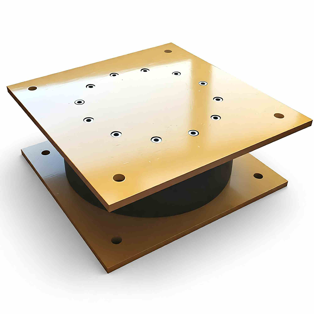
Dual-Function Core: The lead plug within laminated rubber uniquely combines two essential functions: low horizontal stiffness for period lengthening and high, stable hysteretic damping for energy dissipation. This synergy provides superior seismic isolation in a single, reliable device.

Predictable & Stable Hysteresis: The force-displacement behavior is highly predictable, repeatable, and velocity-independent. The lead core yields consistently, creating a stable, fat hysteresis loop that provides significant damping (typically 20-25%) across multiple cycles without degradation.

2. Unmatched Seismic Performance & Life Safety Assurance

The primary advantage is quantifiable risk reduction for both structures and occupants.

Dramatic Force Reduction: By decoupling the superstructure from ground motion and dissipating energy, LRBs can reduce seismic forces transmitted to the structure by 70-80% or more compared to a fixed-base condition.

Protection of Non-Structural Elements: By controlling inter-story drift, LRBs protect critical building contents (medical equipment, servers, fragile architectural features) and ensure the continued operability of essential facilities like hospitals and emergency centers post-earthquake.

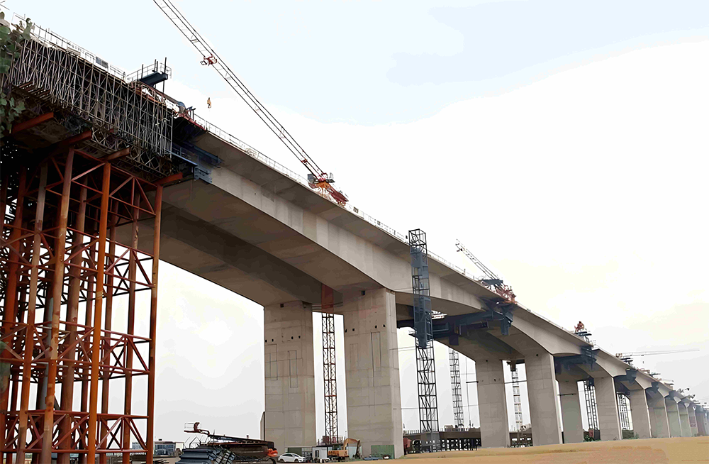
Application-Specific Optimization: We engineer isolators with different shear moduli (0.3-0.7 MPa for buildings, 0.7-1.2 MPa for bridges) to perfectly match the dynamic requirements and load characteristics of the specific structure.

3. Long-Term Reliability and Minimal Lifecycle Cost

Our LRBs are an investment in decades of worry-free performance.

Maintenance-Free Design: The system is hermetically sealed—the lead core is fully encapsulated, and rubber compounds include anti-oxidants and anti-ozonants. This results in zero routine maintenance requirements for the core isolation function over its 25-50+ year design life.

Durability Under Extreme Conditions: Designed to withstand multiple Design Basis Earthquakes (DBE) and Maximum Considered Earthquakes (MCE) without performance loss. The lead core possesses a unique self-annealing property, recrystallizing at room temperature to restore its properties after yielding.

Corrosion & Environmental Resistance: External steel components are protected by high-specification coatings (hot-dip galvanizing or advanced paint systems per ISO 12944), ensuring durability even in harsh marine or industrial environments.

4. Design & Construction Efficiency

The benefits extend into the design and construction phases, saving time and cost.

Simplified Structural Design: By drastically reducing seismic forces, LRBs allow for more economical superstructure design—potentially lighter framing, smaller structural members, and less reinforcement.

Straightforward Installation: Supplied as pre-fabricated, ready-to-install units with clear connection details (bolted or grouted). No complex on-site assembly or calibration is required, minimizing field labor and schedule risk.

Proven Compliance & Easy Validation: Manufactured in full compliance with all major international codes (AASHTO, ASCE 7, EN 15129). We provide comprehensive prototype test reports from accredited labs, simplifying the approval process for engineers and authorities.

5. Tangible Value for All Stakeholders

The advantages translate into concrete benefits for every party in the project chain:

For Owners & Operators: Protection of capital investment, assurance of business continuity, dramatically reduced insurance premiums in seismic zones, and a lower total cost of ownership through minimal maintenance.

For Engineers & Specifiers: A proven, code-compliant technology that provides a clear, defensible path to meeting stringent life-safety performance objectives. It enables innovative architectural forms by removing seismic design constraints.

For Contractors & Project Managers: A logistically simple, schedule-friendly product with reliable lead times and robust packaging. It reduces construction complexity and associated risks.

Competitive Differentiation: Why Our LRB Stands Apart

Our specific engineering and manufacturing approach elevates the standard LRB concept:

Material Science Excellence: We use specially formulated, high-stability Natural Rubber (NR) and 99.9% pure lead, ensuring consistent, long-term mechanical properties.

Precision Manufacturing: ISO 9001-certified processes guarantee dimensional accuracy, perfect bonding between rubber and steel laminates, and the integrity of the lead encapsulation.

Full Technical Partnership: We provide more than a product—we offer complete technical support, from preliminary system design and modeling assistance to installation supervision and lifecycle documentation.

In essence, choosing our LRB Isolator is not merely purchasing seismic hardware; it is adopting a philosophy of resilient design. It delivers a passive, robust, and cost-effective shield against seismic risk, transforming a severe threat into a managed event and providing peace of mind for the lifetime of the structure.


LRB Isolator - Installation & Construction Philosophy

The installation of a Lead Rubber Bearing (LRB) isolator transcends standard construction placement. It represents the critical juncture where engineered design theory transitions into physical, long-term seismic performance. Our approach is founded on treating installation not as a singular task, but as a comprehensive, precision-driven system. This philosophy ensures the inherent reliability of the LRB is fully realized and preserved for the structure's entire lifecycle, delivering on the promise of seismic resilience from the moment the first anchor is set.

Precision Execution: A Phased Methodology for Guaranteed Outcomes

We achieve faultless installation through a meticulously controlled, three-phase methodology that prioritizes preparation, precision, and verification.

Phase 1: Collaborative Design & Meticulous Preparation

Success is engineered before reaching the site. We initiate every project with a collaborative design review, providing or refining detailed connection drawings, anchor bolt schematics, and sequencing plans that integrate seamlessly with the overall structural and architectural designs. Concurrently, every LRB unit destined for your project undergoes final factory verification against its specific performance certificate. It is then prepared for shipment with protective packaging and clear, unique identification, ensuring full traceability and perfect condition upon arrival. This phase eliminates ambiguity, pre-empts field conflicts, and establishes a unified execution plan for all stakeholders.

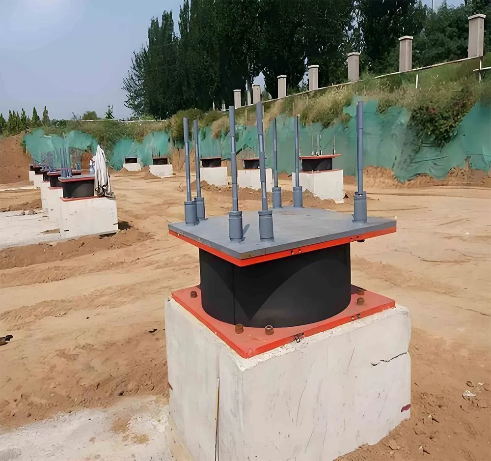
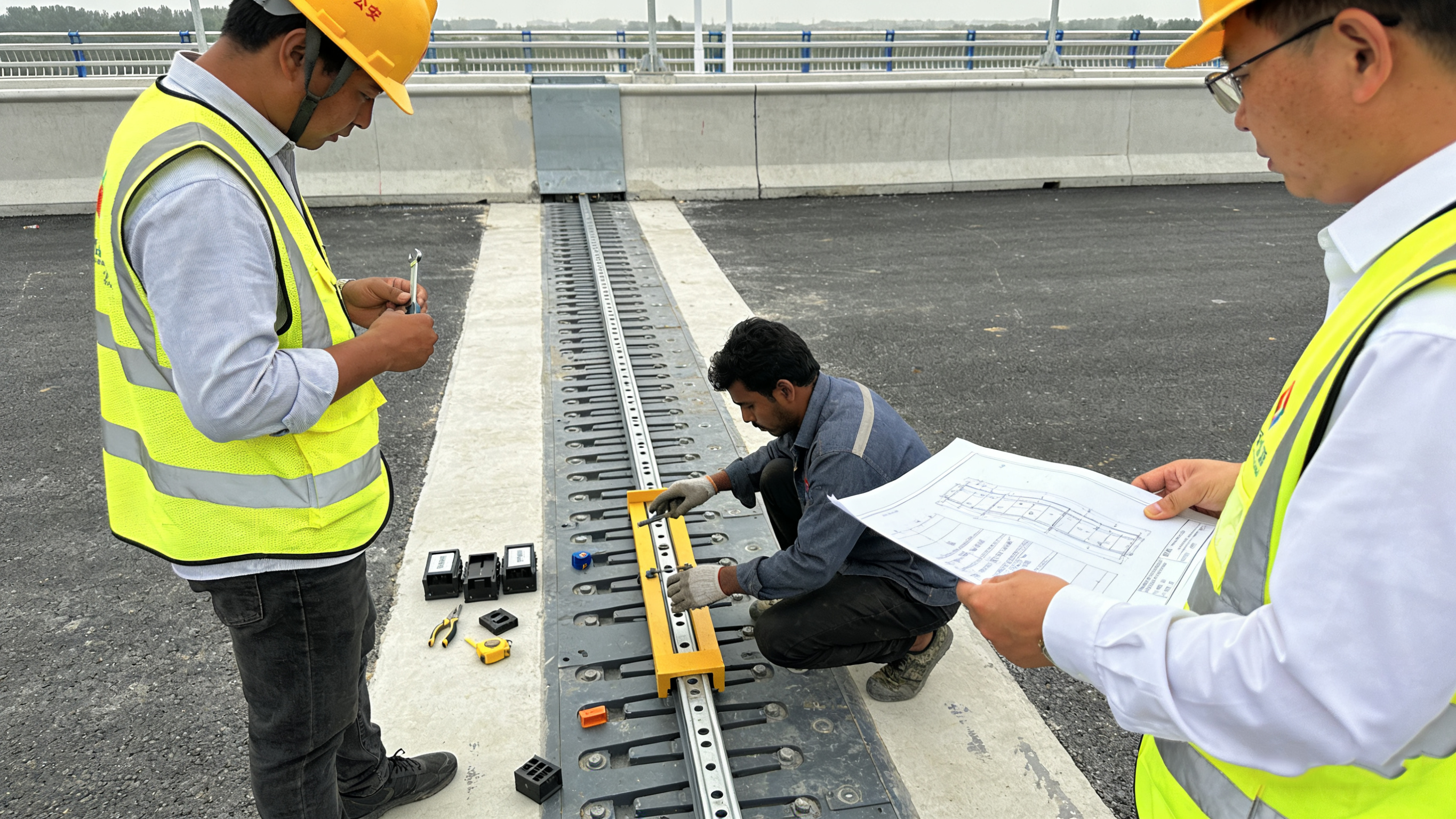
Phase 2: Calibrated Installation & Real-Time Process Control

This is the stage of transformative precision. Guided by our pre-agreed method statements, site teams utilize calibrated instrumentation—such as laser levels and total stations—for millimeter-accurate positioning. The connection process, especially the torquing of high-strength anchor bolts, follows a strict sequential, cross-pattern protocol using calibrated wrenches to guarantee uniform, specification-compliant preload without inducing parasitic stresses. Throughout this hands-on phase, the isolator’s integrity is protected; temporary seals or covers guard against contamination from grout, weld spatter, or debris, preserving its ready-to-function state.

Phase 3: Systematic Verification & Knowledge Handover

Installation is only complete after rigorous validation. We conduct a final multi-point inspection, verifying plan location, elevation, levelness, and the integrity of all connections. Crucially, we ensure all temporary shipping restraints and protective measures are removed, confirming the isolator is in its intended free, unobstructed state to accommodate design movements. The process culminates in a formal handover, where we provide the client with a complete “as-built” dossier. This includes final certified drawings, installation records, torque reports, and most importantly, clear guidance for future visual inspection and maintenance, thereby closing the loop on quality assurance.

Comprehensive Technical Partnership: Embedded Support Across the Project Lifecycle

Our role extends beyond supplying a component; we function as an integrated technical partner from conception through to long-term operation. This partnership is delivered through proactive, phase-specific engagement.

During the Design & Procurement Phase, our engineers work directly with your design team. We provide expert consultation on optimal isolator positioning, interface detailing, and sequencing to avoid construction clashes. This early collaboration ensures the design is not only theoretically sound but also practically executable, optimizing both performance and buildability.

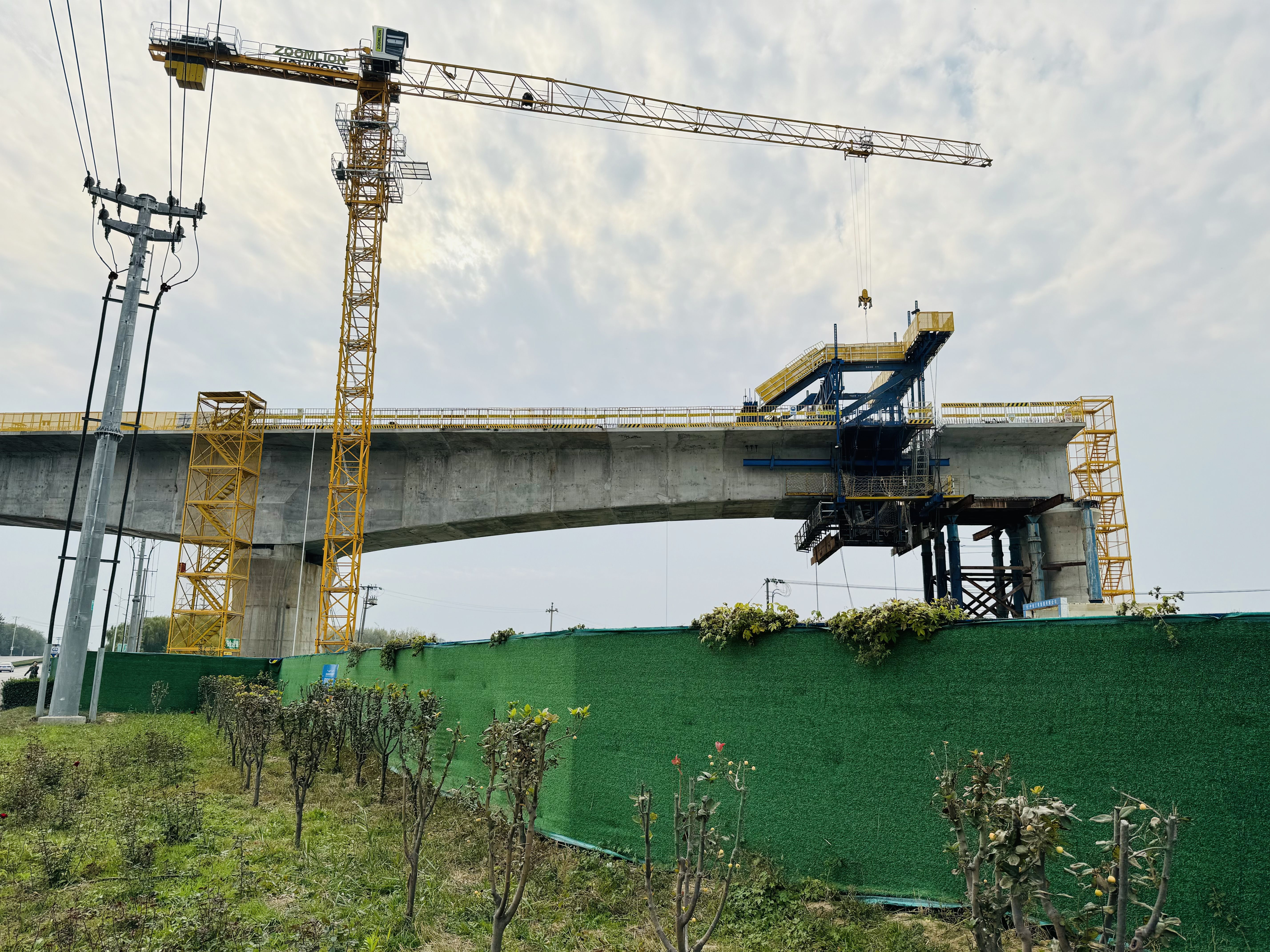
Throughout the critical On-Site Installation Phase, support becomes direct and immediate. We provide access to dedicated technical specialists, available for on-site supervision or remote consultation. Their role is to guide construction crews through critical procedures, offer real-time problem-solving for unforeseen site conditions, and serve as the authoritative source for ensuring the installation strictly adheres to the approved method statements and performance specifications. This presence safeguards quality, bolsters crew confidence, and protects the project timeline.

Finally, our partnership extends into the Commissioning & Operational Phase. We ensure a smooth transition by providing structured training for the owner’s facility management or maintenance teams. This knowledge transfer focuses on practical, routine visual inspection protocols, understanding normal versus atypical conditions, and documenting baseline data for the asset’s life. By empowering the end-user with clear operational knowledge, we ensure the LRB system is not only installed correctly but also understood and managed effectively for decades to come.

In essence, our service transforms a complex engineering challenge into a managed, low-risk, and predictable process. We deliver not just an isolator, but certified performance, assured through precision installation and sustained by enduring technical partnership. This integrated approach is the definitive method to secure the full seismic resilience and lifecycle value engineered into every LRB isolator.


Comparison Reference

Type Load Capacity Movement Capacity Typical Application
Elastomeric Bearing Medium to High Medium Highway / Railway Bridges
Pot Bearing High High Long Span / Heavy Load Bridges
Spherical Bearing Very High High Complex Rotation Structures
Sliding Bearing Medium Very High Large Thermal Expansion Projects

Application Scenarios

Highway Bridge

Highway Bridges

Ideal for highway overpasses and interchange bridges with moderate spans and loads.

Railway Bridge

Railway Bridges

Suitable for railway viaducts requiring vibration isolation and load distribution.

Urban Viaduct

Urban Viaducts

Perfect for elevated roads and urban transit systems in city environments.

Pedestrian Bridge

Pedestrian Bridges

Cost-effective solution for footbridges and light-duty crossing structures.

Technical Documents

Product Datasheet

Complete specifications and dimensions

PDF • 2.4 MB
Download

Installation Guide

Step-by-step installation instructions

PDF • 3.1 MB
Download

CAD Drawings

AutoCAD DWG files for design integration

DWG • 1.8 MB
Download

Test Certificates

Quality and performance test reports

PDF • 1.5 MB
Download

Related Products

Explore more bridge bearing solutions

Need Custom Specifications?

Our engineering team can design bearings tailored to your project requirements