Products

HDRB Isolator

Advanced High-Damping Formulation for Maximum Structural Response Reduction

Providing superior seismic isolation for bridges and critical structures, HDRB bearings ensure long-term performance stability, exceptional energy dissipation, and enhanced safety through cutting-edge elastomeric technology.

WhatsApp: +86 19932366878
Email: info@kingwork.com

HDRB Product Overview

Positioning:

The HDRB (High Damping Rubber Bearing) Isolator represents the pinnacle of modern passive seismic protection technology. Engineered to fundamentally decouple structures from destructive ground motions, it goes beyond conventional base isolation by integrating exceptional energy dissipation directly into its core. This results in a singular, high-performance solution that not only significantly reduces seismic forces and displacements but also ensures long-term reliability and minimal maintenance.

Description:

HDRB Isolators are advanced structural components designed to absorb and dissipate seismic energy at the foundation level. Constructed from specially formulated, high-damping rubber compounds layered with steel plates, they provide a unique combination of vertical load support, horizontal flexibility, and inherent damping. This innovative design dramatically lowers the transmission of earthquake forces to the superstructure, protecting both the integrity of the building or bridge and the safety of its occupants. The product is the result of cutting-edge material science and engineering, developed for projects where safety, resilience, and performance are non-negotiable.

Ideal for a wide range of structures, including:

Bridges & Viaducts: Protects critical transportation infrastructure, ensuring serviceability and preventing catastrophic failure during and after seismic events. Ideal for expansion joints, piers, and abutments.

Essential & Critical Facilities:

Hospitals & Emergency Response Centers: Guarantees operational continuity when it is needed most.

Data Centers & Communication Hubs: Safeguards sensitive equipment and prevents costly downtime.

Power Plants & Utility Stations: Maintains the functionality of vital lifeline infrastructure.

High-Rise & Mid-Rise Buildings: Enhances safety and comfort in commercial, residential, and mixed-use towers by reducing floor acceleration and structural damage.

Heritage & Historically Significant Structures: Provides superior protection with a minimally invasive design, preserving irreplaceable architecture.

Industrial Facilities: Shields complex machinery, production lines, and hazardous material storage from seismic disruption.

In summary, the HDRB Isolator is the definitive choice for engineers and developers seeking a robust, proven, and integrated solution to achieve seismic resilience, offering unparalleled protection for the world’s most important bridges and buildings.


HDRB Isolator
HDRB Isolator - General Technical Specifications
High Damping Rubber Bearing for Seismic Isolation
ParameterSpecification Range / Value
Physical Characteristics
Standard Diameter Range (mm)400 - 1500 (custom diameters available up to 2000mm)
Total Height Range (mm)150 - 700 (proportional to diameter)
Rubber Layer Thickness (mm)8 - 20 per layer (typically 10-15mm)
Steel Plate Thickness (mm)3 - 8 (designed for full stress transfer)
Shape ConfigurationCircular (standard), Rectangular (available)
Load Capacity
Vertical Design Load Range (kN)500 - 20,000 (higher capacities available)
Allowable Vertical Pressure (MPa)5 - 8 (standard range)
Horizontal Design LoadTypically 8-15% of vertical design load
Safety Factor (Vertical)≥ 2.5 (ultimate load / design load)
Mechanical Properties
Equivalent Damping Ratio (%)12 - 18 (standard range at 100% shear strain)
Effective Horizontal Stiffness (Keff) (kN/mm)0.5 - 10.0 (function of diameter and rubber thickness)
Vertical Stiffness (kN/mm)200 - 4,000 (typically 300-500 × horizontal stiffness)
Post-Elastic Stiffness Ratio0.08 - 0.15 (bilinear model K2/K1 ratio)
Shear Strain Capacity (%)≥ 200 (up to 250% available)
Displacement Performance
Design Displacement (DBE) (mm)150 - 500 (475-year return period)
Maximum Displacement (MCE) (mm)200 - 650 (2475-year return period)
Shear Displacement / Diameter RatioTypically ≤ 100% (for optimal stability)
Rotation Capacity (rad)≥ 0.01 (for structural rotations)
Environmental & Durability
Design Service Life≥ 25 years (standard)≥ 50 years (with proper maintenance)
Operating Temperature Range (°C)-30 to +60 (standard)-40 to +70 (extended range available)
Aging Performance (after 50 years)Stiffness change ≤ 20%Damping change ≤ 25%
Compliance & Testing
Prototype TestingCompression, shear, durability, aging, and failure mode tests
Production Testing100% visual and dimensional inspection; sample mechanical testing
Applicable StandardsAASHTO, EN 15129, ISO 22762, GB/T 20688, ASCE 7


Notes:
1. These are general specifications for preliminary design.
2. Actual values depend on specific project requirements and customization.
3. All designs require prototype testing for validation.
4. Consult manufacturer for project-specific solutions.


Key Advantages of HDRB Isolators

1. Integrated High Damping Performance

Technical Superiority: The energy dissipation mechanism is intrinsically embedded within the specially formulated rubber compound, eliminating the need for auxiliary damping devices. This integrated design delivers a consistent equivalent damping ratio of 15–18%, where energy is dissipated through internal friction and hysteresis of the rubber molecular structure during seismic events.

User Benefit: Designers are relieved from the complexity of specifying and coordinating separate damping components. This simplification leads to more reliable and predictable system performance, streamlined analysis, and fewer connection details.

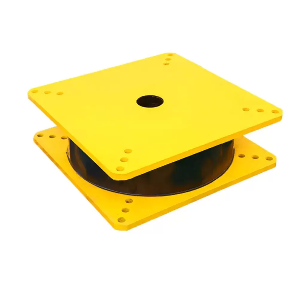
2. Dual-Functionality in a Single Unit

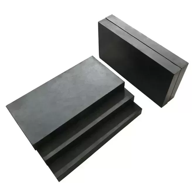
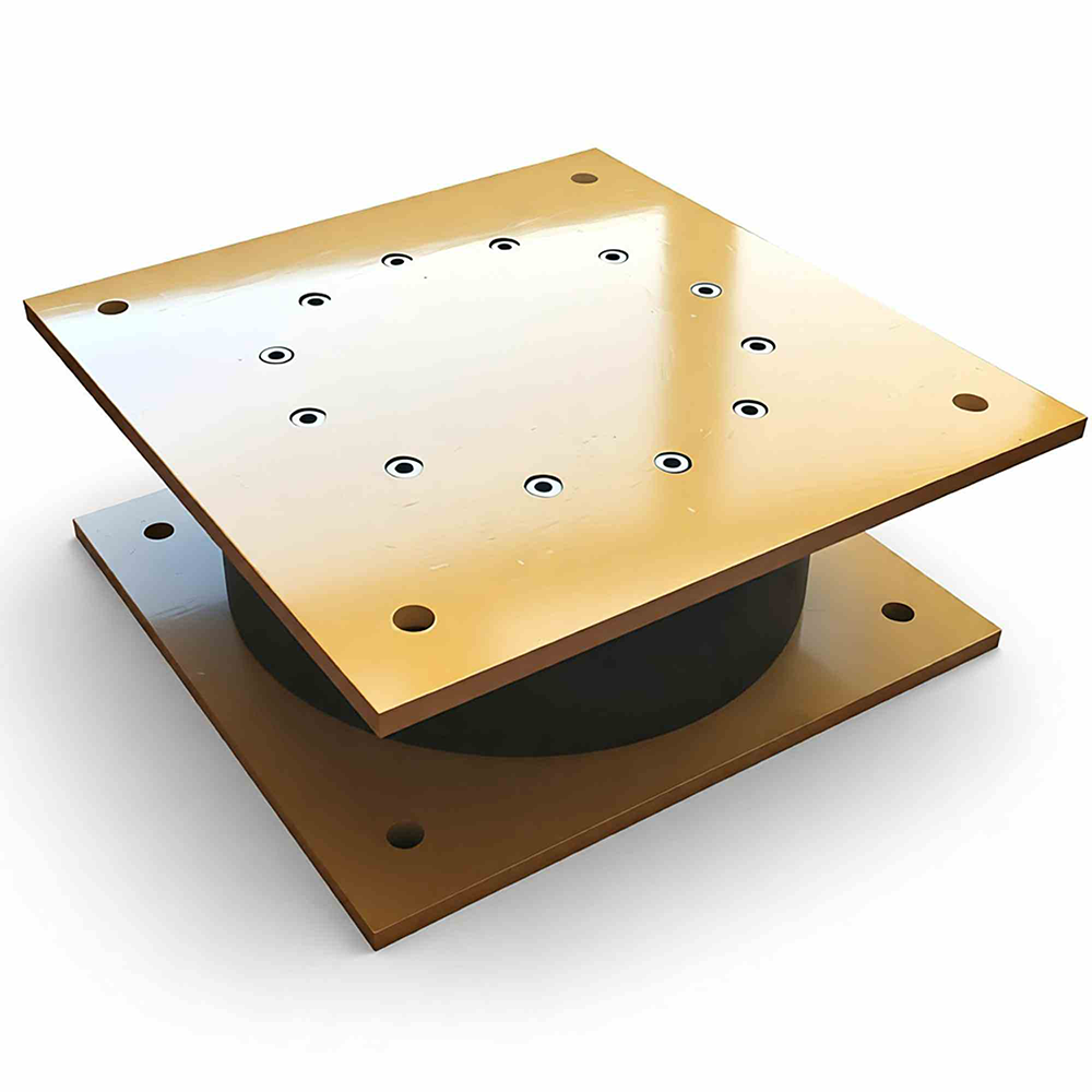
Technical Superiority: A single HDRB isolator seamlessly provides high vertical load-bearing capacity and effective horizontal seismic isolation. The advanced rubber compound maintains high vertical stiffness while offering controlled lateral flexibility and self-centering force. Embedded steel plates ensure uniform stress distribution under compressive loads.

User Benefit: This consolidation reduces the number of system components, minimizing installation complexity, potential points of failure, and long-term maintenance requirements. It simplifies the structural analysis model significantly.

3. Predictable and Long-Term Stable Performance

Technical Superiority: Rigorously controlled manufacturing processes and material formulations ensure exceptional product consistency. Accelerated aging tests confirm that stiffness variation remains within 20% over a simulated 50-year service life, with stable hysteresis loops and no risk of sudden performance degradation.

User Benefit: Provides a reliable foundation for precise engineering analysis and predictable structural response. Long-term stability reduces lifecycle maintenance costs and uncertainties, safeguarding the investment.

4. High Deformation Capacity with Stability

Technical Superiority: The optimized laminate construction allows for stable operation under shear strains exceeding 200%, with a buckling load significantly higher than the design load. This ensures residual load-carrying capacity even during beyond-design-basis seismic events.

User Benefit: Offers a crucial safety margin, helping to prevent catastrophic collapse and supporting performance objectives ranging from "Life Safety" to "Immediate Occupancy" after a major earthquake.

5. Environmental Resilience and Durability

Technical Superiority: The rubber compound includes anti-oxidant and anti-ozonant additives, with a standard operational temperature range of -30°C to +60°C (extendable upon request). Protective external covers can be provided for harsh environments.

User Benefit: Suitable for a wide variety of geographical and climatic conditions, from cold regions to hot climates, enhancing project applicability and reducing design constraints.

6. Advanced Manufacturing and Quality Assurance

Technical Superiority: Production utilizes automated vulcanization presses with real-time process monitoring. Every steel plate is treated, each rubber layer is controlled, and 100% of units undergo dimensional verification, complemented by comprehensive prototype and batch sample testing.

User Benefit: Guarantees that product performance matches design specifications with minimal variance, providing engineers with high-confidence data and eliminating performance uncertainty.

7. Superior Life-Cycle Cost-Effectiveness

Technical Superiority: Compared to conventional seismic-force-resisting systems or hybrid isolation solutions, HDRBs offer optimized life-cycle cost efficiency. Savings are realized through reduced structural member sizes, simplified construction, and minimal maintenance needs.

User Benefit: Delivers an excellent return on investment through both lower initial costs and reduced long-term operational expenses, which is particularly compelling for commercial and public projects.

Summary of Core Value Proposition

HDRB isolators represent the optimal synergy between material science innovation and practical engineering design, delivering a high-performance, reliable, and cost-effective seismic protection solution. Their fundamental value is demonstrated through:

Proven Technical Excellence: Integrated high damping with verified long-term performance.

Uncompromising Reliability: Robust design with significant safety margins for extreme events.

Total Cost Advantage: Favorable initial and life-cycle economics.

Universal Applicability: Adaptable to diverse structural types and environmental conditions.

Designer-Friendly: Simplifies the analysis, specification, and construction process.

For projects prioritizing the balanced achievement of safety, reliability, constructability, and economy, HDRB isolators offer a globally proven solution. They empower all stakeholders—designers, owners, and contractors—to confidently meet and exceed modern seismic performance objectives, creating more resilient and sustainable infrastructure.


HDRB Installation & Construction

Core Philosophy: Precision Meets Practicality

HDRB isolators are engineered not only for superior seismic performance but also for straightforward, reliable, and efficient installation. The design philosophy prioritizes constructability, minimizing on-site labor, specialized tool requirements, and potential for error, thereby translating engineering excellence into tangible project schedule and cost savings.

1. Pre-Installation: Planning for Success

Design Coordination & Preparation

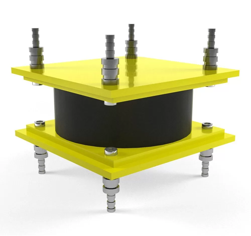
Standardized Connection Details: HDRBs feature pre-designed, standardized bolted or welded connection plates, seamlessly integrating with common structural steel or reinforced concrete detailing. Comprehensive installation drawings are provided for each project.

Clear Interface Definition: Precise requirements for supporting surfaces (flatness, levelness, and elevation) are established upfront, ensuring substrate readiness.

Just-in-Time Delivery: Bearings are shipped as complete, pre-assembled units with protective packaging, arriving on-site ready for installation, eliminating on-site assembly or vulcanization.

User Benefit: Reduces design coordination time, prevents interface clashes during construction, and ensures all necessary components arrive as a single, accountable package.

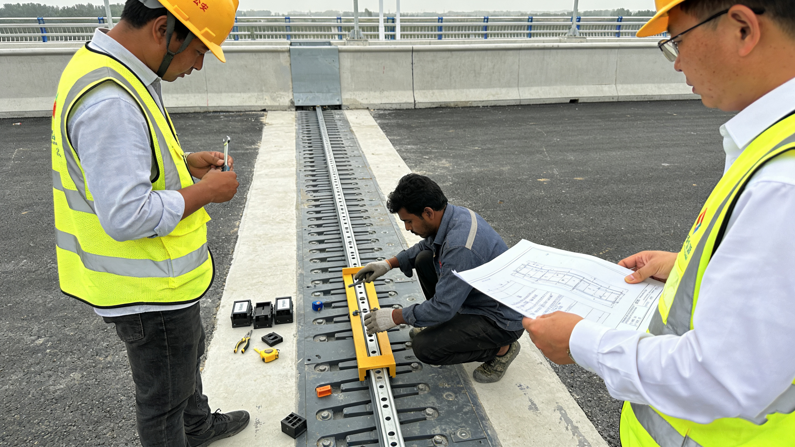
2. Core Installation Process: Streamlined and Controlled

The installation is a systematic, multi-stage process designed for accuracy and safety.

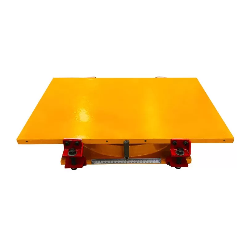
Stage 1: Positioning & Temporary Support

Bearings are placed onto their designated locations using standard lifting equipment.

Temporary positioning aids or shims may be used to hold the bearing at the correct elevation and alignment before final connection.

Stage 2: Final Connection

For Bolted Connections: High-strength bolts are torqued to specified values in a calibrated sequence, ensuring uniform load transfer. This method allows for potential future inspection or replacement.

For Welded Connections: Pre-welded shear plates on the HDRB are welded to embedded plates in the structure following qualified welding procedures. This provides a permanent, rigid connection.

The process requires only standard construction trades (ironworkers, welders) without highly specialized skills.

Stage 3: Alignment Verification & Clearance

Final horizontal alignment and elevation are verified using survey equipment.

The required seismic gap (clearance around the bearing for unimpeded movement) is confirmed to be clear of all obstructions like utilities, permanent walls, or grade beams.

User Benefit: A logical, step-by-step process familiar to construction crews, minimizing downtime and leveraging existing site equipment and labor.

3. Key Installation Advantages & Tolerances

Simplified Alignment: HDRBs are designed to accommodate practical field tolerances. While precise, requirements for plan position (±5mm) and levelness (1/500 gradient) are achievable with standard construction practices.

Integrated Protection: Many designs include a protective outer cover that is installed concurrently, guarding the rubber from UV exposure, debris, and incidental damage during subsequent construction phases.

Minimal Curing/Wait Time: Unlike some foundation elements, no curing or setting time is required post-installation, allowing immediate progression to the next construction activity.

4. Quality Assurance & Inspection

A robust QA process ensures installed performance matches design intent.

Pre-Installation Inspection: Visual check for shipping damage and verification of bearing identification against drawings.

In-process Verification: Monitoring of bolt torque values or weld quality (visual or NDT).

Post-Installation Report: Documentation including as-built location photos, torque records, and survey verification forms is compiled, providing a clear quality trail.

User Benefit: Provides owners and engineers with documented confidence in the installation integrity and creates a benchmark for future maintenance inspections.

5. Safety During Construction

Inherent Stability: The bearings are stable under the construction (vertical) load alone, with lateral resistance provided by temporary restraints if needed until the superstructure is completed.

Clear Procedures: Step-by-step method statements mitigate risks associated with lifting and positioning heavy components.

6. Maintenance & Long-Term Accessibility

Ease of Inspection: The design allows for visual inspection of critical external features with minimal effort. Protective covers are often removable for periodic in-depth checks.

Design for Serviceability: Considerations for potential future bearing inspection, monitoring, or even replacement are factored into the initial design of the isolation interface and seismic gap.

Summary: The Constructability Advantage

The installation methodology for HDRB isolators is a critical component of their value proposition. By transforming a high-tech seismic protection device into a practical, constructible building component, we deliver significant benefits across the project timeline:

For Contractors: A predictable, efficient installation scope using familiar techniques, supporting schedule adherence and cost control.

For Engineers: Reduced risk of installation errors and reliable as-built performance matching analytical models.

For Owners: Lower installed cost, minimized construction complexity, and confidence in the long-term serviceability of their seismic investment.

Ultimately, the true measure of an engineered product is not just its laboratory performance, but its seamless integration into the built environment. HDRB isolators are designed to excel in both realms, delivering advanced protection through a fundamentally straightforward and robust construction process.


Comparison CategoryLead Rubber Bearing (LRB)High-Damping Rubber Bearing (HDRB)Friction Pendulum Bearing (FPB)
CORE ISOLATION MECHANISM & OPERATING PRINCIPLE


Fundamental Working PrincipleElastomeric + Hysteretic Damping: Combines linear elasticity of rubber with plastic energy dissipation of a central lead core. The lead yields at a defined force, providing stable, predictable damping.Viscoelastic Damping: Uses specially compounded rubber with high inherent damping properties. Energy is dissipated internally through viscous/elastic deformation of the rubber material itself.Sliding + Gravity Restoration: Utilizes an articulated slider on a spherical concave surface. Energy is dissipated through sliding friction, and recentering is provided by the gravity-induced rise of the slider.
Primary Source of Energy DissipationPlastic deformation (yielding) of the confined lead core.Internal viscoelastic hysteresis of the rubber compound during cyclic shear.Coulomb friction between the slider and the polished concave surface.
Primary Recentering (Self-Centering) ForceElastic restoring force of the rubber. Recentering is good but not full; some residual displacement is typical.Elastic restoring force of the rubber. Similar to LRB, recentering is good but not perfect.Gravity-based restoration. The geometry of the spherical surface automatically guides the structure back to center, providing excellent, inherent recentering.
KEY PERFORMANCE CHARACTERISTICS & DESIGN PARAMETERS


Typical Effective Stiffness (Keff)0.5 - 15 kN/mmStiffness has a distinct bi-linear characteristic due to lead yield.0.3 - 10 kN/mmStiffness is more linear but amplitude-dependent.Primarily a function of supported weight and radius: K = W / R"Stiffness" is constant for a given design.
Equivalent Viscous Damping Ratio (ξ)20% - 30%Highly stable and predictable across cycles. Largely independent of velocity.10% - 20%Varies with strain amplitude, temperature, and loading frequency.10% - 20% (or higher with multi-surface designs)Dependent on friction coefficient and displacement (ξ = 2μ/πD for simple FP).
Characteristic Strength (Q) / Yield ForceWell-defined and fixed by the lead core area. Q ≈ σy * Alead.Not explicitly defined. Resistance builds gradually with strain.Friction force. Q = μ * W, where μ is the friction coefficient.
Performance SensitivityLow sensitivity to loading rate. Moderate sensitivity to temperature (affects rubber, minimal effect on lead).High sensitivity to strain amplitude, temperature, and loading frequency (velocity).Sensitivity to velocity (μ varies), temperature at sliding interface, and wear over extreme cycles.
MATERIALS & CONSTRUCTION


Core Materials• Natural Rubber (NR) laminates• Pure lead core• Steel shims and plates• Specially formulated High-Damping Rubber (carbon black, oils, resins)• Steel shims and plates• Polished stainless steel concave surface• Composite/PTFE/UHMWPE/UHPF-based slider• Self-lubricating liner
Inherent Durability & AgingExcellent. Lead is inert and sealed. Rubber is protected. Design life 50+ years.Good. High-damping compounds may have higher long-term creep and property changes than NR.Very good. Sealed sliding surfaces. Performance depends on wear resistance of liner. No aging of core mechanism.
APPLICATIONS & SELECTION GUIDANCE


Ideal Project Profiles• Bridges (high stiffness, stable damping)• Buildings requiring predictable, high damping• Critical facilities (hospitals, data centers)• Structures with medium to long periods• Buildings where simplicity and lower cost are priorities• Low to mid-rise buildings• Regions with moderate seismicity• Long-period structures (tall buildings)• Buildings where explicit recentering is critical• Structures with very large displacement demands• Heavy structures (nuclear, industrial)
Key Advantages• Robust, predictable hysteresis• High, stable damping• Mature, extensively code-recognized technology• Good vertical load capacity• Simpler monolithic construction (no lead plug)• Lower initial unit cost• Good for multi-directional motion• No heavy metal (lead) concerns• Excellent inherent recentering• Period is mass-independent (tunes itself)• Can accommodate very large displacements• Compact for given capacity
Limitations / Considerations• Contains lead (handling/recycling)• Limited in ultra-large displacements• Residual displacements possible• Damping is amplitude/temperature sensitive• Lower damping capacity than LRB• Potential for greater property variation• More complex mechanical assembly• Friction coefficient variability• Higher unit cost• Potential for tonal "chatter"
Typical Cost PositioningModerate to HighCost-effective for its high performance and reliability.Low to ModerateOften the most economical isolator option.HighPremium cost for high-performance and recentering capabilities.


Application Scenarios

Highway Bridge

Highway Bridges

Ideal for highway overpasses and interchange bridges with moderate spans and loads.

Railway Bridge

Railway Bridges

Suitable for railway viaducts requiring vibration isolation and load distribution.

Urban Viaduct

Urban Viaducts

Perfect for elevated roads and urban transit systems in city environments.

Pedestrian Bridge

Pedestrian Bridges

Cost-effective solution for footbridges and light-duty crossing structures.

Technical Documents

Product Datasheet

Complete specifications and dimensions

PDF • 2.4 MB
Download

Installation Guide

Step-by-step installation instructions

PDF • 3.1 MB
Download

CAD Drawings

AutoCAD DWG files for design integration

DWG • 1.8 MB
Download

Test Certificates

Quality and performance test reports

PDF • 1.5 MB
Download

Related Products

Explore more bridge bearing solutions

Need Custom Specifications?

Our engineering team can design bearings tailored to your project requirements