Viscous Fluid Damper: Key Advantages & Strategic Value
The Core Distinction: Velocity as the Design Parameter
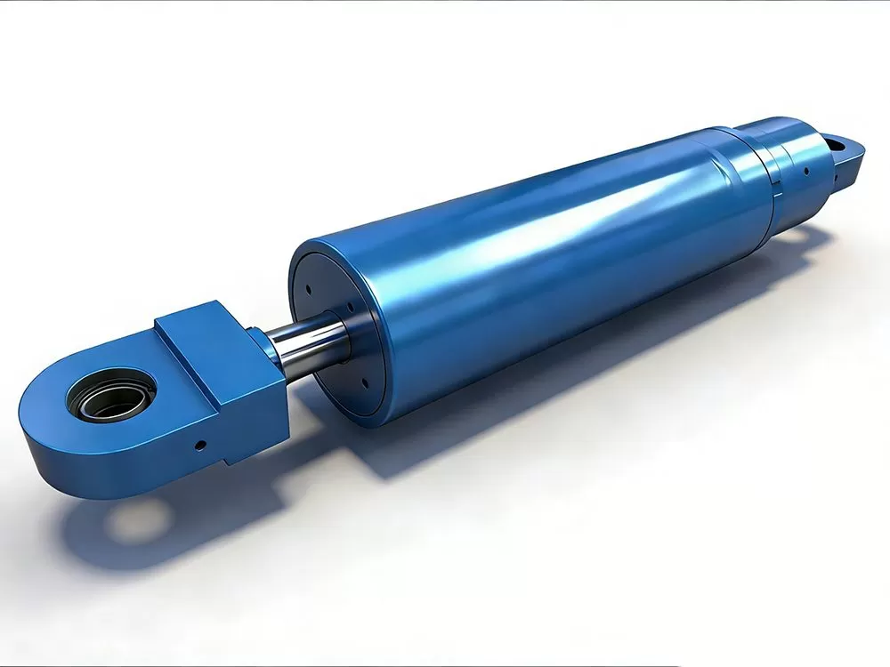
The fundamental superiority of the Viscous Fluid Damper (VFD) stems from its unique operating principle: it is a purely velocity-dependent device. Unlike displacement-based systems (like yielding metallic dampers) or stiffness-altering systems (like braces), the VFD generates a resisting force proportional to the velocity of structural motion, described by F = C·V^α. This singular characteristic unlocks a suite of unmatched advantages for modern structural engineering, offering a tool of exceptional precision, versatility, and reliability for dynamic control.
1. Targeted Energy Dissipation Without Stiffness Penalty
Technical Superiority: The VFD operates as a pure energy sink. It dissipates kinetic energy through viscous fluid shear without adding significant lateral stiffness to the primary structural system. This allows structural engineers to design the main frame for optimal strength and ductility, while using VFDs to surgically control dynamic responses. The damping force is perfectly out-of-phase with displacement, meaning it applies maximum resistance precisely when the structure's velocity is highest—during peak vibrational cycles—providing the most efficient energy removal possible.
User Trust Driver: For designers, this means no compromise on architectural or structural layout. Dampers can be integrated without forcing major redesigns to accommodate increased stiffness. For retrofit projects, it is a game-changing advantage, as adding substantial damping is often possible without the costly foundation upgrades that stiffening systems would require.
2. Predictable, Tunable, and Analytically Verifiable Performance
Technical Superiority: The damper's behavior is defined by two clear engineering parameters: the damping coefficient (C) and the velocity exponent (α). These can be precisely tailored to match a structure's specific dynamic signature—its natural frequencies, mode shapes, and target performance objectives. The resulting force-velocity relationship is highly predictable and can be accurately modeled in any modern structural analysis software, yielding reliable performance forecasts.
User Trust Driver: This calculability transforms dynamic design from an art into a verifiable science. Engineers gain confidence that the installed system will perform as analyzed. Owners and regulators receive a clear, physics-based justification for the solution, backed by prototypes tested to exact specifications, reducing project approval risk and liability concerns.
3. Exceptional Versatility Across Hazard Types and Structural Systems
Technical Superiority: A single VFD technology platform effectively addresses multiple dynamic threats: seismic shaking, wind-induced vibrations (including vortex shedding and buffeting), pedestrian-induced motion, and even blast or impact loads. By selecting the appropriate α value, the damper's response can be optimized for each scenario—e.g., a low α (e.g., 0.3) for seismic force-limiting, or a linear α (1.0) for predictable wind response.
User Trust Driver: This provides a future-proofed, multi-hazard resilience solution. A building or bridge protected against earthquakes is also inherently more comfortable and durable against daily wind events. It represents a comprehensive investment in structural integrity and occupant well-being, maximizing the return on investment.
4. Inherent Force-Limiting Capability for Ultimate Safety
Technical Superiority: With a velocity exponent α < 1 (a common design choice), the VFD exhibits a nonlinear, self-regulating characteristic. As velocity increases during an extreme event, the rate of force increase diminishes. This "saturation" effect creates a natural upper bound on the forces transmitted to the structure's connections, columns, and foundations.
User Trust Driver: This acts as a built-in safety fuse, protecting critical—and often expensive—structural elements and connections from being overstressed. It provides a crucial safety margin for beyond-design-basis events, safeguarding the primary investment and ensuring the structure's survival and repairability.
5. Sealed, Passive, and Maintenance-Free Longevity
Technical Superiority: Modern VFDs are hermetically sealed, pressurized units with no external power requirements, moving mechanical linkages, or fluids that require replenishment. The advanced silicone-based fluid and multiple redundant seals are engineered for a 50- to 100-year service life with guaranteed performance stability across extreme temperature ranges (-40°C to +70°C).
User Trust Driver: For owners and facility managers, this translates to zero operational cost and zero scheduled maintenance after installation. Unlike active systems or devices with consumable parts, the VFD is a "install and forget" component, drastically reducing the total cost of ownership and eliminating long-term operational risk.
6. Global Provenance and Code Acceptance
Technical Superiority: VFD technology is supported by decades of rigorous academic research, extensive laboratory testing, and documented successful performance in real-world events across the globe. It is explicitly recognized and codified in all major international design standards (AASHTO, ASCE 7, EN 15129, IBC, Eurocode 8, etc.).
User Trust Driver: This provides unassailable credibility and facilitates regulatory approval. Specifiers can propose the solution with confidence, knowing it is a well-understood and accepted technology by building officials and peer reviewers worldwide. Its proven track record in iconic structures (skyscrapers, long-span bridges, historic landmarks) serves as powerful testament to its reliability.
Summary: The Value Proposition for All Stakeholders
The Viscous Fluid Damper is not merely a product; it is an enabler of advanced, performance-based design.
For the Structural Engineer: It is a precision analytical tool that provides unparalleled control over a structure's dynamic response, enabling the design of lighter, more elegant, and more resilient structures while simplifying complex retrofit challenges.
For the Architect: It offers design freedom, allowing ambitious forms and slender profiles to be realized without compromising safety or comfort, as damping can be integrated discreetly.
For the Project Owner/Operator: It represents strategic risk capital—an investment that protects the asset's value, ensures business continuity, minimizes lifecycle costs, and enhances the safety and comfort of occupants.
For the Contractor: It provides a standardized, installable component with clear procedures, simplifying construction sequencing and quality assurance.
Ultimately, the VFD’s greatest advantage is its ability to deliver certainty in the face of dynamic uncertainty. It provides a robust, reliable, and analytically transparent means to ensure that structures not only remain standing but continue to function safely and comfortably, today and for generations to come.
Viscous Fluid Damper: Installation & Construction Methodology
Core Philosophy: Engineering for Seamless Integration
The installation of a Viscous Fluid Damper (VFD) system is engineered with one paramount objective: to transform advanced damping technology into a straightforward, reliable, and predictable construction activity. Recognizing that the most sophisticated engineering is only as good as its field implementation, our approach prioritizes constructability, precision, and comprehensive support, ensuring the designed performance is faithfully realized in the built structure with minimal risk and disruption to the project schedule.
Phase 1: Pre-Installation Engineering & Coordination
Design Integration & Interface Management
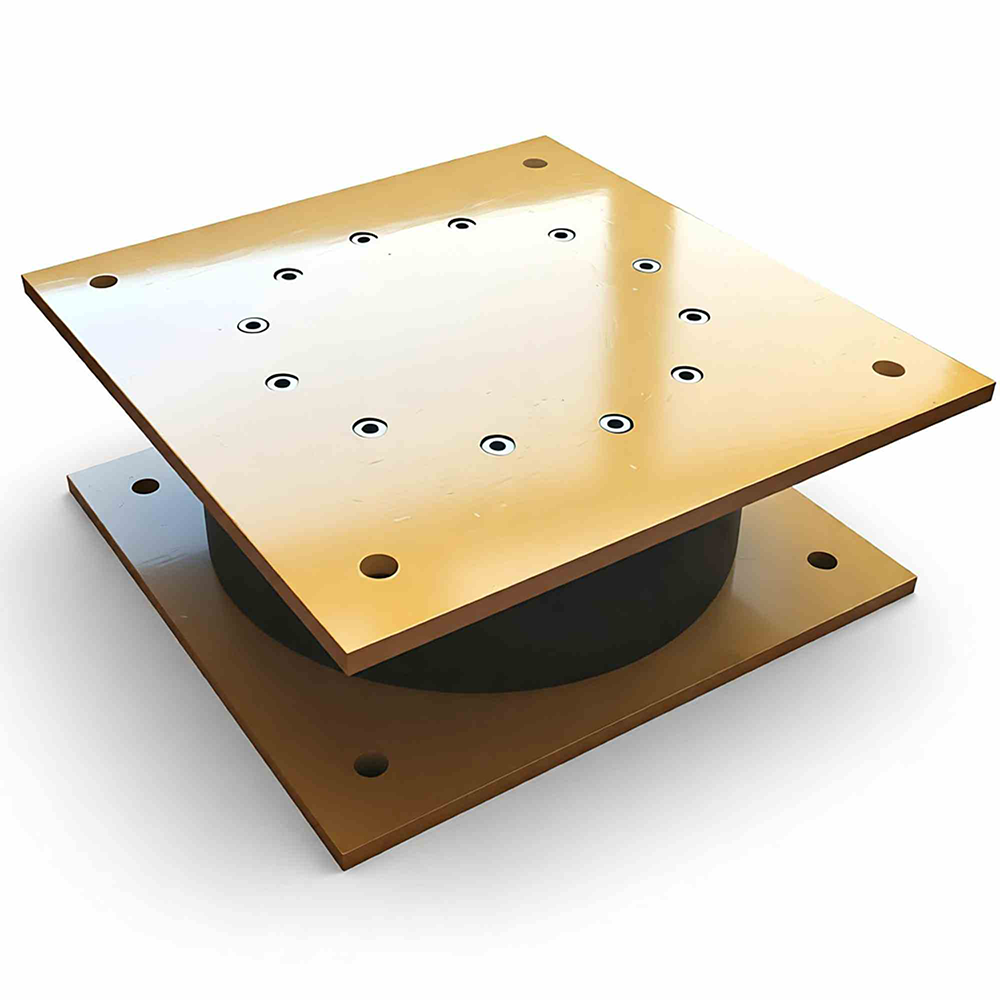
Prior to fabrication, our engineering team engages in a detailed collaborative process with the project's structural engineers and architects. This phase focuses on interface resolution, ensuring the damper's connection details—clevis pins, gusset plates, mounting brackets—are perfectly coordinated with the surrounding steel or concrete elements. We provide fully detailed shop drawings, 3D BIM models, and interface control documents that leave no ambiguity for the fabricator and erector.
Site-Specific Method Statement & Sequencing
We develop a project-specific Installation Method Statement (IMS) that integrates seamlessly with the overall construction schedule. This document defines:
Lifting and handling procedures tailored to site crane capacity and access limitations.
Temporary support and alignment requirements before final connection.
The precise installation sequence, particularly critical in retrofit projects where live load or temporary stability is a concern.
Coordination points with other trades (e.g., welding of connection plates during steel erection, coring/casting of anchors in concrete).
Logistics & Pre-Delivery Verification
Each damper is a fully assembled, tested, and sealed unit upon delivery. It arrives with:
Protective shipping restraints to prevent accidental stroking during transit.
Environmental caps on rod ends to protect the precision piston rod.
A complete "as-built" dossier including factory test reports, material certifications, and a unique serial number for traceability.
All necessary installation hardware (pins, bolts, spacers) with certified material reports.
Phase 2: Field Installation Process
Step 1: Positioning & Temporary Support
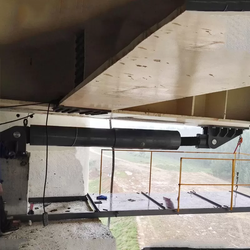
The damper is lifted into place using standard rigging, guided by survey-controlled location points. Temporary braces or adjustable props hold the unit in its nominal position, allowing for fine adjustments without imposing any load on the damper itself. This step requires no activation of the damper's internal mechanism.
Step 2: Final Connection & Alignment
The connection is typically made via high-strength pins or pre-installed bolted flanges.
For Pin Connections: Pins are inserted into pre-drilled holes in the damper clevis and the structural gusset plates. Shim plates are used as needed to account for mill tolerances, ensuring a snug fit without binding. Final pin installation follows a specified procedure to avoid damaging the damper's bearings or seals.
For Bolted Connections: High-strength bolts are installed and torqued to specified values in a calibrated sequence to ensure uniform load distribution.
Alignment Verification: Throughout the connection process, laser alignment tools or surveying equipment verify that angular and parallel misalignment tolerances (typically ±2° and<3mm) are="" maintained="" to="" prevent="" the="" induction="" of="" parasitic="" forces.="">
Step 3: Removal of Shipping Restraints & Commissioning
Once the damper is fully connected and the structure is under its permanent load (or a defined temporary load state), the shipping restraints are carefully removed according to a prescribed sequence. This "release" is a critical milestone, transitioning the damper from a static component to an active, ready-to-function device. A final visual and dimensional inspection confirms the installed configuration matches the design intent.
Technical Superiority in Field Implementation
"Plug-and-Play" Simplicity
The VFD's greatest installation advantage is its self-contained, passive nature. There are:
No field-assembled hydraulic lines to plumb and pressure-test.
No electrical connections, control cabinets, or power supplies to install and commission.
No sensitive tuning or calibration required on-site.
No special curing or setting periods, unlike grouted or post-tensioned systems.
This dramatically reduces the required specialized trade expertise and eliminates entire categories of potential field errors.
Built-in Tolerance Accommodation
The damper's rod-end spherical bearings are designed to accommodate the realistic angular and parallel misalignments encountered in steel and concrete construction. This built-in forgiveness prevents the installation from becoming a source of costly rework or induced stresses, protecting both the project schedule and the damper's long-term performance.
Phase 3: Quality Assurance, Documentation & Support
Comprehensive Installation Record
We ensure a verifiable quality trail through:
Torque Calibration Reports: For all installation tools.
As-Built Survey Reports: Documenting final installed coordinates and alignments.
Signed Inspection Checklists: For each critical step (restraint removal, pin installation, etc.).
Digital Photographic Log: Time-stamped photos of key stages.
Multi-Tiered Technical Support
On-Site Technical Representative: For first-of-a-kind installations or complex projects, a factory engineer provides direct oversight, conducts toolbox talks with crews, and performs final sign-off.
Remote Expert Support: 24/7 availability for real-time consultation via video call to resolve unforeseen site questions.
Detailed Installation Manuals: Step-by-step, illustrated guides specific to the damper model and connection type.
Addressing Unique Project Challenges
Seismic Retrofit & Live-Structure Installation
For retrofit projects, our methodology includes specialized protocols for:
Phased installation sequences that maintain structural stability throughout.
Temporary bracing schemes to compensate for the temporary removal of existing elements.
Load monitoring during the transfer of forces to the new damper system.
Extreme Environment Installations
Procedures are adapted for:
Marine/Coastal Sites: Enhanced handling to prevent saltwater contamination of rod surfaces before seal engagement.
Arctic/Cold Climates: Pre-conditioning and handling protocols to protect seals and fluids.
Confined Spaces: Specialized lifting and rigging plans for limited-access areas like bridge towers or building cores.
The Constructability Advantage: Summary
The Viscous Fluid Damper installation philosophy delivers decisive value across the project chain:
For the Contractor: A predictable, low-risk work package. It utilizes familiar skills (rigging, bolting, pinning), fits into standard sequences, and has clear, achievable tolerances. It avoids the schedule and cost uncertainties associated with complex field-assembled systems.
For the Design Engineer: Assurance that design intent is achieved. The pre-coordinated interfaces and clear procedures minimize the risk of errors that could compromise system performance. The passive nature means the as-built behavior will match the analytical model with high fidelity.
For the Project Owner: Confidence in quality and long-term reliability. The comprehensive documentation provides a permanent record of correct installation. The maintenance-free design means no future operational costs or access requirements, securing the asset's value for its entire lifespan.
In essence, we engineer not just the damper, but the entire process of bringing it to life within a structure. By making the installation of this advanced technology as routine as installing a standard structural brace, we remove the final barrier to adopting superior dynamic performance, ensuring that the resilience designed on paper becomes a reality in steel and concrete.
.webp)
.webp)
.webp)