Modular Joint Expansion Engineering:High-Movement Bridge Solutions
Bridge engineers and infrastructure owners face a persistent challenge: accommodating substantial thermal movements, creep, shrinkage, and seismic actions without compromising deck continuity or ride quality. Standard single-gap joints become impractical when total movements exceed 200 mm. This is where modular joint expansion systems demonstrate their engineering value. Designed for displacement capacities ranging from 400 mm to over 2000 mm, these systems integrate multiple support bars, central beams, and elastomeric sealing elements. This article provides a deep technical examination of the mechanics, application criteria, and reliability improvement strategies for modular expansion joints in modern bridge construction.
1. Core Architecture of Modular Joint Expansion Systems
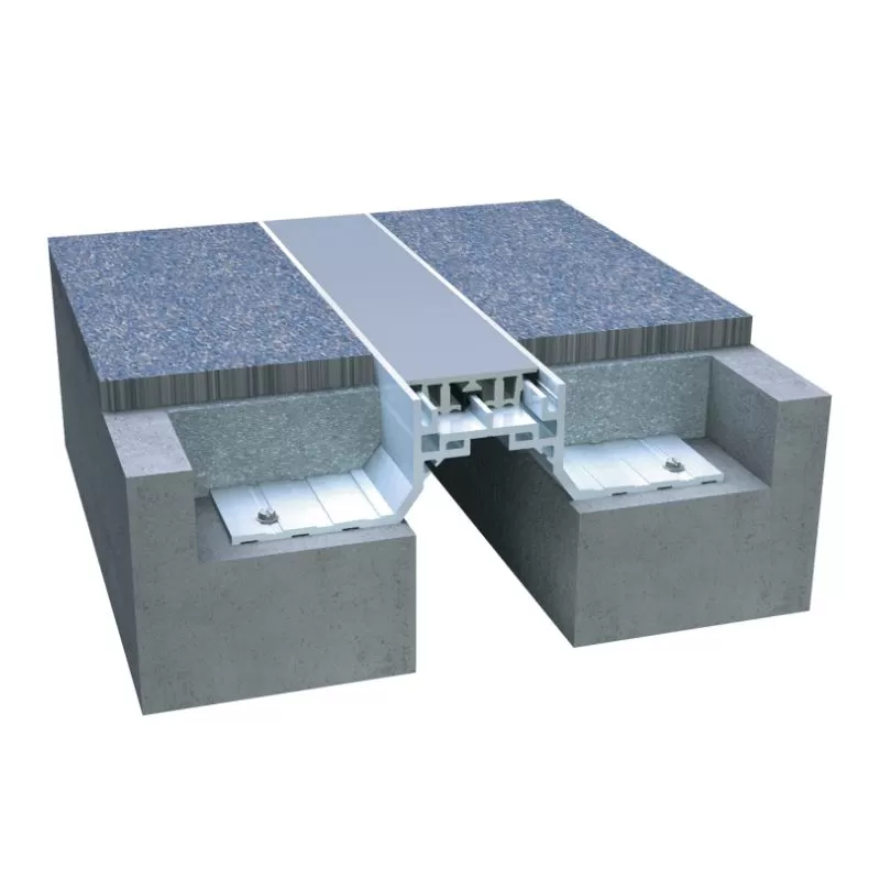
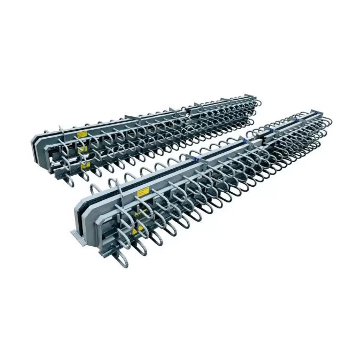
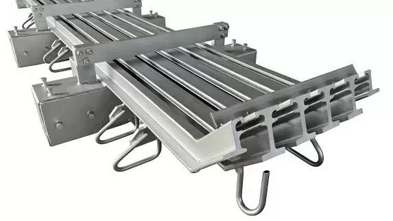
Unlike simpler strip seal or finger joints, a true modular joint expansion assembly consists of several load-carrying beams that move independently while maintaining a continuous surface for vehicle loads. The core functional components include:
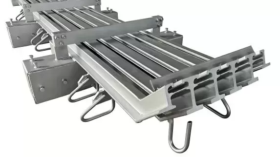
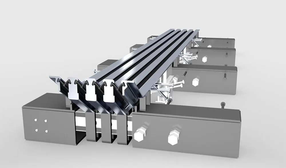
Central beams (multiple parallel profiles): Directly support wheel loads and transfer them to the underlying support bars.
Support bars (transverse or longitudinal configuration): Distribute vertical and horizontal forces across the joint opening, often guided by sliding bearings.
Elastomeric sealing profiles: Pre-filled or compression seals that prevent water and debris ingress while accommodating beam displacement.
Control boxes / displacement control units: Mechanical or hydraulic regulating elements that ensure synchronized movement of central beams.
The performance of any modular joint expansion solution depends on the precise interaction of these components under millions of load cycles. According to AASHTO LRFD Bridge Design Specifications, the joint must maintain serviceability at the maximum gap opening as well as under repetitive fatigue loading. A high-quality modular joint expansion design also integrates redundancy: the failure of a single central beam does not lead to immediate structural compromise, which is a critical safety factor for high-traffic viaducts.
2. Engineering Parameters That Govern Service Life
Selecting an appropriate modular joint expansion requires evaluating displacement demands, traffic volume, environmental exposure, and seismic criteria. The most relevant technical parameters are:
Total movement capacity (longitudinal & transverse): Determined by bridge length, coefficient of thermal expansion, and bearing layout. For a steel box girder bridge with 300 m span, daily thermal movement often exceeds ±150 mm, making modular solutions mandatory.
Fatigue resistance class: According to EN 1993-2 or AASHTO specifications, the joint details must resist 2 million cycles at specified load ranges without crack initiation. Full-penetration welds and high-grade S355NL or S460N steel are typical.
Watertightness class: High-performance elastomeric seals (e.g., EPDM or chloroprene rubber) certified to IP67 equivalent bridge standards prevent chloride penetration into substructures.
Vibration and impact attenuation: Special damping elements integrated into the support bar guides reduce dynamic amplification factors caused by heavy truck passages.
Field studies indicate that approximately 60% of premature joint failures originate from inadequate waterproofing or corrosion of support bars. By specifying a fully encapsulated modular joint expansion with hot-dip galvanized or duplex coating systems, engineers can extend the maintenance interval beyond 25 years under severe de-icing salt exposure.
3. Solving Common Field Performance Deficiencies
Infrastructure managers report recurrent issues with conventional expansion joints: leaking seals, beam fracture, loosened anchor bolts, and noise generation. A well-engineered modular joint expansion directly addresses these pain points through specific design remedies:
Seal extrusion and leakage: Modern systems use pre-compressed elastic seals with integrated retaining lips that maintain contact pressure even when the gap opens to maximum design width. Additionally, redundant sealing (primary + secondary) is available for sensitive environments.
Uneven load distribution causing beam bending: Finite element optimization of the support bar spacing and cross-sectional inertia reduces relative deflection under HS-25 or LM1 loads. Dynamic validation using full-scale prototypes is advisable for capacities >1000 mm.
Progressive loosening of anchorage: Epoxy-injected post-installed bars combined with shear pockets eliminate creeping under cyclic shear forces. For new decks, embedded steel frames with headed studs provide positive mechanical locking.
Accumulated debris blockage: The geometry of the modular joint expansion can be designed with self-cleaning slopes and wider bottom channels, reducing maintenance cleaning frequency.
From a life-cycle reliability perspective, modular systems outperform multiple single-gap joints because each central beam shares the total movement, lowering stress concentrations. For rehabilitations where existing joint seats have limited depth, custom low-profile modular joint expansion units can be manufactured without altering the wearing course level.
4. High-Demand Application Scenarios
While all long-span bridges can benefit from modular technology, four scenarios present unique challenges that demand specialized engineering:
4.1 Cable-stayed and suspension bridges
These structures experience not only thermal displacement but also live-load deflection and wind-induced oscillations. A modular joint expansion designed for such bridges must incorporate multidirectional movement capability (longitudinal, transverse, and rotational degrees of freedom). Rotational bearings below the support bars allow for deck end rotation up to ±0.02 rad without binding.
4.2 Seismic zones with high ductility requirements
During a design earthquake, relative displacements can exceed 400 mm in a few seconds. Modular joint expansion systems configured with shock transmission units or damped control boxes prevent impact damage at the closure strip. End stops with replaceable energy-absorbing cartridges further protect the main structure.
4.3 Railway bridges (ballasted or direct-fastened)
Dynamic amplification factors are considerably higher for rail traffic. Stiffness grading and fatigue-tested weld details are mandatory. Additionally, the modular joint expansion assembly must guarantee electrical continuity for track circuits; alternative non-conductive central beam coatings can be applied where needed.
4.4 Extreme climate regions (large daily温差)
Desert and arctic environments produce daily temperature fluctuations above 30 °C. The sealing elastomers must maintain flexibility from -40 °C to +80 °C. Special low-temperature grade EPDM or silicone seals are recommended for modular joint expansion in such climates.
5. Installation Precision and Quality Assurance Workflow
Even superior designs fail if installation deviates from specifications. A robust installation procedure for any modular joint expansion consists of these critical steps:
Site measurement and gap verification: Prior to delivery, the actual gap geometry at mean temperature is surveyed using 3D laser scanning. Adjustment factors for installation temperature are calculated.
Setting of prefixed shims and support bars: The complete unit is lowered into the prepared recess and aligned with road gradients. Laser leveling ensures the central beam surface does not deviate more than ±1.5 mm from the adjacent pavement.
Backfill concrete casting: High-early-strength, shrinkage-compensated concrete or polymer mortar is placed around the anchorages. Vibration elimination during curing prevents voids that could cause loosening.
Functional performance testing: After curing, hydraulic jacks open and close the modular joint expansion through its full movement range while monitoring beam parallelism and seal compression.
Non-destructive testing (ultrasonic or magnetic particle) of all load‑carrying welds should be documented. For large infrastructure projects, bearing pad stiffness tests are performed on-site to confirm friction coefficients align with design assumptions.
6. Why KINGWORK Delivers Reliable Modular Joint Expansion Engineering
With over two decades specializing in bridge components and seismic protection devices, KINGWORK combines precision manufacturing with advanced material science. Every modular joint expansion system leaving the production facility complies with EN 14889 or AASHTO MP standard after full-scale prototype testing under simulated traffic and weather cycles. KINGWORK’s engineering team provides site-specific design calculations, including finite element verification of complex load cases, ensuring that each modular joint expansion matches the movement capacity, support stiffness, and environmental resilience required by the client’s bridge.
Beyond fabrication, KINGWORK supplies detailed installation supervision packages and post-commissioning inspection services. This integrated approach reduces the risk of misalignment and extends the maintenance‑free service period. For engineers looking to specify a proven modular joint expansion solution, KINGWORK offers customization from 400 mm to 1600 mm displacement ranges, with optional seismic dampers and integrated drainage channels.
Frequently Asked Questions (FAQ)
Q1: What is the maximum movement capacity that a single modular joint expansion can accommodate?
A1: Standard designs cover displacements from 400 mm to 2000 mm, depending on the number of central beams and support bar layout. For special projects, capacities up to 2400 mm are achievable with reinforced control boxes. Always refer to site-specific movement analysis.
Q2: How do modular joint expansion systems perform under seismic excitation?
A2: Properly configured units include shock-absorbing end stops and guided sliding assemblies that permit bi-directional movement. During an earthquake, the modular joint expansion can open beyond normal service limits without detachment, protecting the deck from collision. Seismic codes (e.g., AASHTO Guide Specs for LRFD Seismic) require verification of the joint’s ultimate displacement capacity.
Q3: What regular maintenance does a modular joint expansion require?
A3: Annual inspection of seal integrity, debris clearance from drainage channels, and checking of anchorage torque are recommended. Elastomeric seals typically require replacement every 12–15 years, while the steel structure lasts over 30 years with proper corrosion protection. Heavy traffic sites may benefit from biannual inspections.
Q4: Can a modular joint expansion be retrofitted into an existing bridge that has a single-gap joint?
A4: Yes, provided that the existing joint recess depth and width meet the minimum requirements (usually ≥250 mm depth). A transition structure may be cast to adapt the geometry. KINGWORK offers retrofit engineering with customised narrow-profile modular systems, minimizing deck modification.
Q5: How does waterproofing stay effective during large movements of a modular joint expansion?
A5: Pre-compressed elastomeric seals are installed with initial compression of 30-40%. As the joint opens, the seal expands while maintaining contact pressure against the beam sides. Additional side dams and drainage channels capture any minor leakage. For extreme environmental requirements, dual-seal configurations provide redundancy.
Ready to specify or upgrade a modular joint expansion for your bridge project? Consult KINGWORK’s technical department for displacement calculations, custom design drawings, and installation support. Submit your project parameters (bridge span, design movement range, traffic class) through the official inquiry form to receive a comprehensive engineering proposal tailored to your infrastructure needs. Ensure long-term safety and performance with field-proven modular joint expansion solutions from KINGWORK.
For inquiries: please contact KINGWORK’s engineering team via the official website or email your bridge specifications directly. Our experts typically respond within 48 hours with initial feasibility analysis and technical documentation.