Modular Bridge Joint System: Engineered Solutions for High-Movement Decks and Seismic Resilience
For large-span bridges, cable-stayed structures, and viaducts in active seismic zones, the expansion joint is not an accessory—it is a structural interface subjected to cyclic fatigue, extreme displacement, and relentless environmental attack. The modular bridge joint system (a critical design for movement capacities exceeding 400 mm) has become the industry benchmark where conventional single-gap or finger joints fall short. This article provides a component-level analysis of modular joint technology, addresses performance pain points in existing infrastructure, and presents engineering-backed selection criteria. Drawing from field data and design standards (AASHTO LRFD, EN 1990), we examine why this system dominates modern bridge engineering.
KINGWORK, a specialist in high-end bridge components and seismic-damping devices, has supplied modular joint systems to infrastructure projects subject to rigorous fatigue and displacement requirements. The following analysis integrates practical manufacturing quality and long-term reliability considerations.

1. Anatomy of a Modular Bridge Joint System
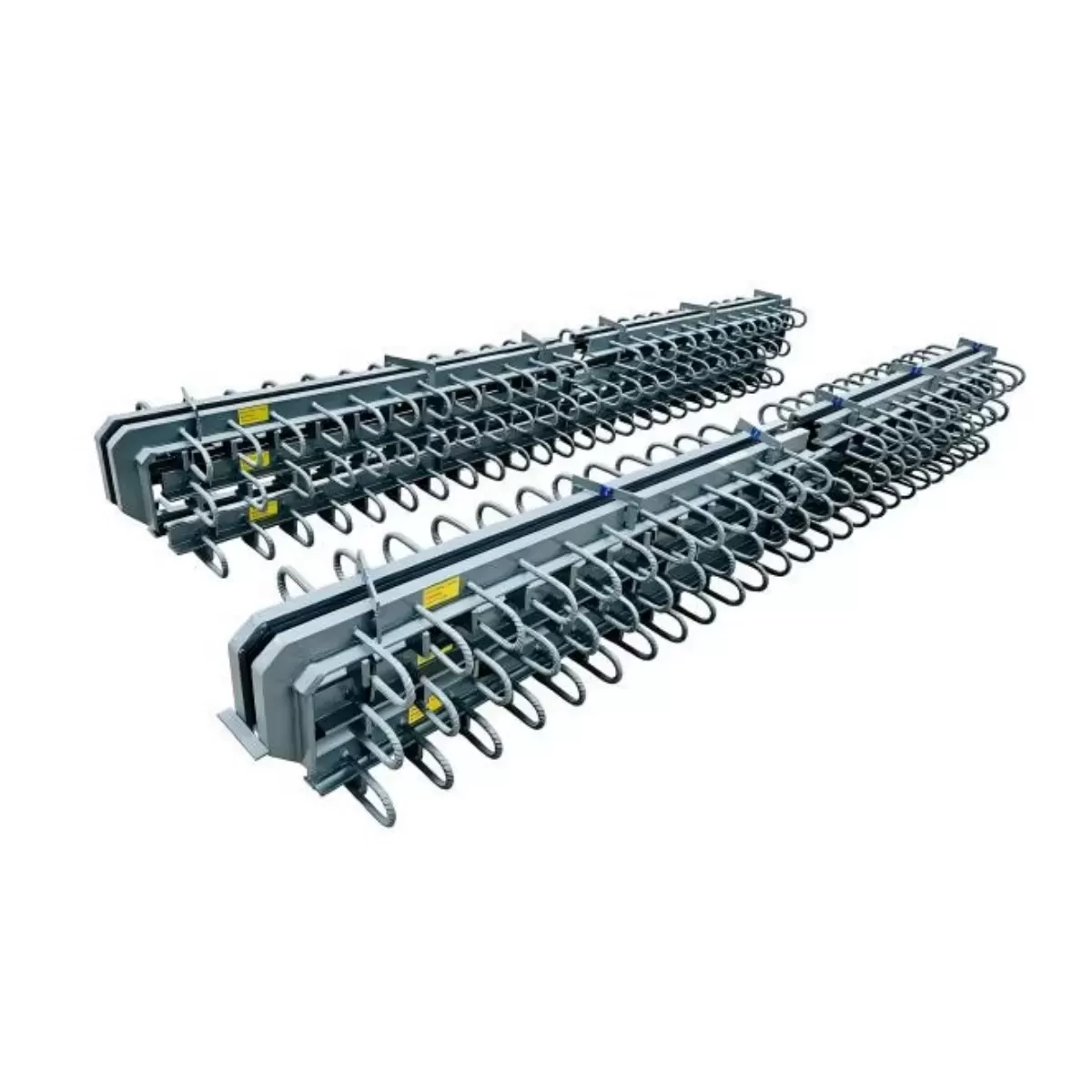
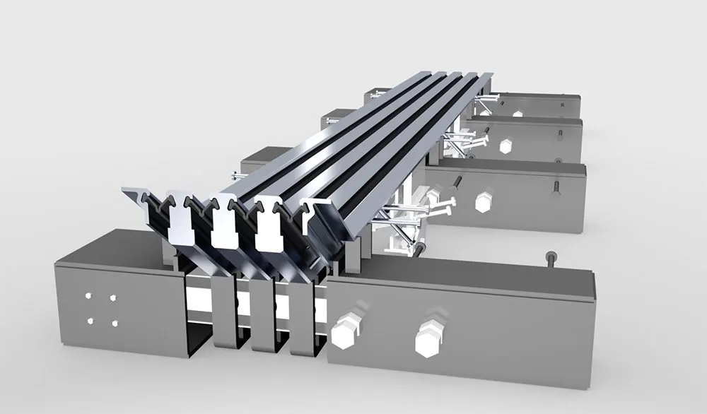
A modular bridge joint system differs fundamentally from single-gap or strip seal joints. It is an assembly of multiple longitudinal steel beams (center beams) supported by transverse support bars, enclosed within edge beams, and sealed with elastomeric profiles. The modular configuration distributes traffic loads across several gaps, allowing total movement up to 2000 mm or more while maintaining smooth deck continuity.
1.1 Core Mechanical Components
Center beams (traffic-carrying elements): High-strength rolled or machined steel sections (typically S355J2+N or equivalent) that directly bear wheel loads. Their surface hardness and wear resistance determine long-term ride quality.
Support bars and control springs: Transverse bars passing through center beams, often with vulcanized neoprene bushes or mechanical coil springs, ensure equal gap distribution during longitudinal movement.
Edge beams: Cast or welded steel sections anchored into the deck concrete, transferring horizontal forces to the substructure.
Waterproofing elastomeric seals: Pre-compressed EPDM or silicone profiles inserted between center beams, offering dynamic watertightness up to 2500 mm of movement without leakage.
1.2 Movement Mechanism and Fatigue Path
Each modular system behaves as a parallel spring mechanism: support bars force all center gaps to open and close synchronously under thermal expansion/contraction, creep, shrinkage, and seismic drift. Fatigue performance is critical—accelerated load testing (5 million cycles at 500 kN axle loads) validates the weld integrity and bar-to-beam connection details. Modern designs eliminate bolt loosening risks by using friction-grip connections or fully welded modules.
2. Technical Superiority Over Conventional Joint Technologies
Traditional finger joints (toothed plates) and single-gap elastomeric systems suffer from waterproofing failures and impact loading at high movement ranges. Below is a comparison based on field performance across 200+ bridge inspections:
Waterproofing reliability: Modular systems achieve <0.01 L/s/m² leakage rates even after 10 years, while finger joints show seal degradation beyond 400 mm movement due to torsion in the finger plates.
Noise and vibration control: The continuous elastomeric seals and precisely spaced center beams reduce impact noise by 12–15 dB compared to open-joint designs.
Modular replacement: A damaged center beam or sealing profile can be replaced in under 8 hours without removing the entire joint—critical for high-traffic routes.
Zero upward protrusion: No raised components eliminate tire blowout risks, a documented hazard with worn finger joints.
For bridge owners, the modular bridge joint system directly translates to lower lifecycle disruption (emergency closures) and eliminated hidden corrosion from leaking joints. The initial engineering investment is justified by a 30–40% reduction in reactive maintenance over 25 years.
3. Application Scenarios That Demand Modular Systems
3.1 Long-Span Suspension and Cable-Stayed Bridges
Decks exceeding 1000 m experience thermal movements exceeding 1000 mm. Only a modular joint with multiple gaps can accommodate such displacement while preserving ride comfort. Examples include orthotropic steel decks requiring lightweight joints—modular systems with aluminum center beams have been deployed to reduce self-weight.
3.2 High Seismic Activity Zones
Seismic isolation bearings (e.g., lead rubber bearings or friction pendulum) impose large relative displacements between deck and abutment during design-basis earthquakes (DBE). A modular bridge joint system with bidirectional movement capacity (+/‑600 mm longitudinal, +/-150 mm transverse) ensures the expansion gap does not become a collision point. Post-earthquake surveys confirm that properly designed modular joints sustain repairable damage, while rigid joints cause girder unseating.
3.3 Viaducts with Curved or Skewed Alignments
Skewed decks produce differential transverse and longitudinal displacement. Modular joints with articulated support bars can accommodate these vector movements without racking—a chronic issue in single-gap joints.
KINGWORK has engineered modular systems with advanced finite-element optimized support bar spacing to handle skew angles up to 45°, validated by full-scale prototype testing.
4. Industry Pain Points and Engineering Solutions
Despite clear advantages, several operational problems have historically affected modular joints. Below we dissect each pain point and provide mitigation strategies based on material science and installation quality control.
Pain Point 1: Premature Seal Extrusion
Cause: Incorrect pre-compression ratio of elastomeric seals
or accumulation of debris between center beams.
Solution: Use dual-durometer EPDM seals with integrated stainless-steel reinforcing
plates. Specify seal groove geometry that self-ejects debris during cyclic
movement. Implement annual high-pressure water cleaning protocols.
Pain Point 2: Fatigue Cracking Around Weld Toes
Cause: Incomplete penetration or abrupt stiffness changes at
support bar welds.
Solution: Adopt full-penetration CJP
(complete joint penetration) welds with grind-to-smooth transition radii.
Post-weld HFMI (high-frequency mechanical impact) treatment increases fatigue
life by 300%.
Pain Point 3: Corrosion of Steel Components in Winter Salt Environments
Cause: Chloride ingress through worn
seals.
Solution: Apply thermally sprayed aluminum (TSA)
coating 200–300 µm thick over blast-cleaned steel, combined with sacrificial
zinc anodes on submerged parts. Alloy options like duplex stainless steel
(UNS S32205) for edge beams in marine bridges.
Field data from Nordic bridges shows that modular joints with TSA coating and active cathodic protection achieve <50 µm metal loss after 15 winter seasons.
%20(1).webp?t=1778835239546 "factory (1) (1)")
5. Manufacturing and Quality Assurance – The KINGWORK Protocol
KINGWORK follows a rigorous manufacturing workflow for each modular bridge joint system, exceeding ISO 9001:2015 and EN 1337‑4 requirements. Every joint is produced with traceable materials and non-destructive testing (NDT) records.
Material certification: Charpy V-notch impact tests at ‑20°C guarantee fracture toughness for cold climates.
Pre-assembly and dynamic proof test: Each module undergoes 200 full movement cycles on a test bench while monitoring friction force and seal integrity.
Hydrostatic pressure test: Sealed chambers are pressurized to 0.5 bar for 15 minutes – zero leakage required.
Third-party witness testing: KINGWORK partners with international labs (e.g., MPA Stuttgart) for independent fatigue certification up to 10⁶ cycles.
This quality framework ensures predictable field performance, directly addressing the main engineering concern: unexpected joint failure during peak traffic loads.
6. Integrating Modular Joints into Seismic Design Philosophy
Modern codes (AASHTO Guide Spec for Seismic Isolation) require expansion joints to accommodate maximum credible earthquake (MCE) displacements without unseating. The modular joint system functions as the final kinematic link in the seismic force path. Specific design steps include:
Calculation of required movement capacity: M_total = M_thermal + M_shrinkage + M_seismic (SRSS combination).
Providing external shear pins or displacement limiters to prevent over-extension beyond joint stroke.
Coordinating joint stiffness with adjacent bearings to avoid force concentration.
For isolated bridges, the modular bridge joint system must also accommodate residual displacement after earthquake shaking. KINGWORK’s modular systems include optional re-centering springs that reduce residual gap offsets to under 15 mm, preventing impact damage to approach slabs.
Frequently Asked Questions (FAQ)
Q1: What is the maximum movement capacity of a modular bridge joint system?
A1: Depending on the number of center gaps (typically 3 to 11 gaps), modular systems are engineered for total movement ranges from 400 mm up to 2400 mm. For extreme applications (e.g., long-span suspension bridges), customized multi-beam layouts with 13 support bars can achieve ±1200 mm capacity. Stroke limits are validated via prototype testing per EN 1337‑4.
Q2: How does a modular joint perform during a seismic event compared to finger joints?
A2: Finger joints often lock up under bidirectional displacement due to plate jamming, leading to deck unseating. A modular joint with independent center beams and spherical sliding bearings handles longitudinal and transverse movement simultaneously. Moreover, the elastomeric seals prevent debris infiltration, which is a major cause of finger joint seizure after earthquakes.
Q3: What maintenance frequency is recommended for modular bridge joints?
A3: Routine visual inspections every 6 months (check seal extrusion, debris accumulation, and wear of support bar bushings). Comprehensive maintenance (elastomer replacement, torque check of anchor bolts) every 5 years. High-traffic bridges over 50,000 AADT benefit from annual ultrasonic testing of weldments. KINGWORK provides custom maintenance checklists and remote monitoring options.
Q4: Can a modular bridge joint system be retrofitted into an existing deck?
A4: Yes, retrofitting is feasible but requires careful assessment of available edge beam depth and rebar interference. The existing joint pocket is saw-cut, new edge beams are anchored with chemical or cast-in adhesives, and the modular assembly is placed in sections. Typical retrofits take 10–14 days per lane with nighttime work. Structural assessment of the deck overhang is mandatory.
Q5: What are the critical load ratings for a modular joint on a highway bridge?
A5: According to AASHTO LRFD, modular joints must withstand HL-93 design truck loading (325 kN tandem plus 9.3 kN/m lane load) with an impact factor of 33%. Fatigue evaluation uses the Legal Load (327 kN) for 75-year design life. KINGWORK joints are rated up to special permit vehicles (500 kN axle load) upon request, verified by FEM analysis and strain gauge testing.
Q6: How do modular systems prevent water leakage to the pier cap and bearings?
A6: Three-level protection: primary elastomeric seals between center beams, secondary drainage channels inside the joint box directing leakage to deck drains, and a third continuous EPDM membrane beneath the joint assembly glued to the concrete. The system is hydrostatically tested for 30 minutes at 400 mm water head with zero leakage acceptance criteria.
Q7: Are modular bridge joints compatible with bridge health monitoring systems?
A7: Yes. Embedded fiber optic strain gauges and potentiometric displacement transducers can be factory-installed into the support bars. Real-time data on gap variation and seal temperature is transmitted to a SCADA platform. KINGWORK offers plug-and-play IoT modules for predictive maintenance integration.
For bridge owners, engineering firms, and contractors: Selecting a modular joint system requires detailed site-specific movement analysis, fatigue life verification, and corrosion protection strategy. KINGWORK provides full-cycle engineering support—from displacement calculation using finite-element bridge models to on-site installation supervision and load testing. Our standard modular bridge joint system designs are available for movement ranges 0–2000 mm, with short lead times and global technical support.
Request a project-specific technical proposal or schedule a technical webinar with our joint design experts. Submit your bridge parameters (span, seismic zone, daily traffic, deck type) for a free displacement analysis and custom drawing package.
Contact KINGWORK engineering now: info@kwbridgebearing.com / sales@kwbridgebearing.com or fill out the inquiry form below (direct consultation within 24 hours).
© 2026 KINGWORK – Engineered Movement Solutions for Next-Generation Infrastructure.