How Optimal Bridge Expansion Joint Replacement Minimizes Lifecycle Costs
 (1).webp)
Bridge expansion joints are small components that carry disproportionate structural responsibility. Representing less than 2% of a bridge's total construction cost, their failure is responsible for over 60% of superstructure and substructure deterioration. According to data from the Federal Highway Administration (FHWA), water infiltration through leaking joints is the primary accelerator of chloride-induced rebar corrosion and concrete spalling in pier caps and abutments.
When structural degradation forces rehabilitation, executing a successful bridge expansion joint replacement requires more than simply swapping out old materials for new ones. It demands a holistic understanding of structural movement, material chemistry, and site-specific environmental stressors. This guide provides a deep technical analysis of the joint replacement process, introducing a systematic framework to optimize durability and structural lifetime value.
For decades, municipal authorities and private operators have relied on engineered components from established manufacturers like KINGWORK to protect infrastructure investments. By aligning advanced material selection with rigorous installation practices, engineers can mitigate the recurring costs associated with premature joint failures.
The "Waterproof First" Fallacy: A Different Perspective
In bridge preservation, conventional wisdom states that the primary goal of joint design is to create a completely waterproof barrier. While waterproofing is important, treating it as the sole metric of success often leads to early failure. This is the "Waterproof First" fallacy.
Expansion joints are dynamic structural elements, not static roof membranes. If a replacement strategy focuses exclusively on the seal's water tightness while ignoring the surrounding transition zone's structural dynamics, the joint is highly likely to fail. Under the impact of heavy wheel loads, the interface between the concrete deck and the joint profile experiences extreme shear stresses.
A truly successful bridge expansion joint replacement treats the joint as a three-dimensional drainage and load-transfer system. Water management must include secondary drainage paths beneath the joint to capture runoff when—not if—the primary elastomeric seal undergoes mechanical tearing or environmental degradation over time.
Rather than designing solely for absolute water tightness, engineers should design for "controlled redirection." This perspective shifts the focus toward durable anchorage, high-performance transition materials, and serviceable secondary collection systems.
Analyzing the Failure Mechanisms of Bridge Joints
Before specifying a replacement system, engineers must perform a forensic analysis of why the existing joint failed. Most failures fall into three categories: anchor fatigue, transition zone degradation, and seal rupture.
Anchor fatigue occurs when repetitive dynamic wheel impacts exceed the fatigue limit of the steel studs or concrete reinforcement. This is common in high-traffic corridors where heavy vehicles generate significant dynamic load allowance (IM) factors. Over time, these micro-impacts fracture the weld connection between the anchor loops and the joint's steel edge rails.
Transition zone degradation occurs when the concrete headers on either side of the joint spall under load. Traditional cementitious concretes lack the flexibility to absorb impact loads. When subjected to freeze-thaw cycles and deicing chemicals, the micro-cracks propagate, leading to loose concrete blocks that can damage vehicle tires and expose the joint's steel frame.
The seal itself can fail due to ozone degradation, debris accumulation, or exceeding its maximum movement capacity. When dirt and non-compressible debris fill the joint cavity during cold periods, subsequent warm-weather expansion crushes the elastomer, causing permanent deformation or tearing.
To address these challenges, manufacturers like KINGWORK engineer expansion systems with reinforced anchorages and high-durability seals designed to withstand harsh mechanical and environmental conditions.
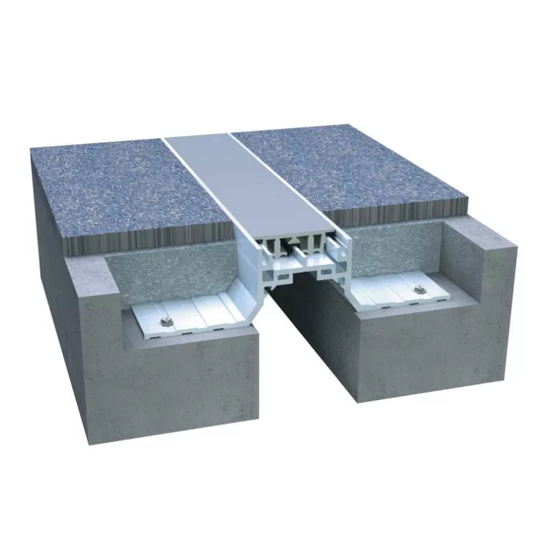
Selecting the Right Replacement System: Modular vs. Strip Seal
Choosing the correct joint type is critical to the longevity of the rehabilitation project. The table below outlines the operational limits and application criteria for the most common replacement systems.
| Joint Type | Max Movement Capacity | Primary Advantages | Typical Applications |
|---|---|---|---|
| Asphaltic Plug Joint (APJ) | ±25 mm | Low initial cost, seamless ride surface, rapid installation. | Short-span bridges, low-movement structures, overlay projects. |
| Strip Seal Joint | Up to 100 mm | Robust steel edge rails, replaceable neoprene gland, reliable sealing. | Medium-span highway bridges, high-traffic arterial roads. |
| Modular Joint System | > 80 mm (up to 1000+ mm) | Accommodates multi-directional movements, high durability, engineered for seismic demand. | Long-span structures, cable-stayed bridges, major highway flyovers. |
Strip seal systems are the standard for mid-range movements. They feature a single neoprene gland locked into steel edge profiles anchored directly to the deck concrete. For movements exceeding 80–100 mm, modular systems are required. These systems use intermediate beams and support bars to distribute the total movement across multiple smaller seals.
While asphaltic plug joints offer a smooth transition, they are susceptible to rutting in hot climates and plow damage in winter. Therefore, for critical infrastructure, strip seals or modular joints are generally preferred to ensure long-term structural integrity.
The Joint Lifecycle Integrity Matrix (JLIM) Framework
To standardize the selection and execution of a bridge expansion joint replacement, we utilize the Joint Lifecycle Integrity Matrix (JLIM). This framework balances three critical engineering vectors to maximize the lifespan of the replacement joint.
Vector 1: Kinematic Alignment (Movement
Profile)
Engineers must calculate the absolute maximum thermal,
shrinkage, creep, and rotational movements at the joint location. Selecting a
joint based solely on nominal longitudinal movement often leads to premature
failure if skew or transverse movements are present.
Vector 2: Transition Zone Toughness (Material
Compatibility)
The interface between the steel joint and the
concrete deck must be constructed using materials that match the modulus of
elasticity of both substrates. Elastomeric concretes are often preferred here,
as they provide a flexible, high-impact-resistant transition that absorbs
dynamic wheel loads and protects the joint anchors.
Vector 3: Active Drainage Management (Secondary
Systems)
No seal remains completely watertight forever. The JLIM
framework requires a secondary drainage system—such as a continuous synthetic
trough positioned beneath the joint—to direct infiltrated water away from
vulnerable substructure components.
By applying the JLIM framework during the design phase, engineers can avoid the common mistake of treating joint replacement as a simple cosmetic repair, ensuring the new installation survives its intended design life.
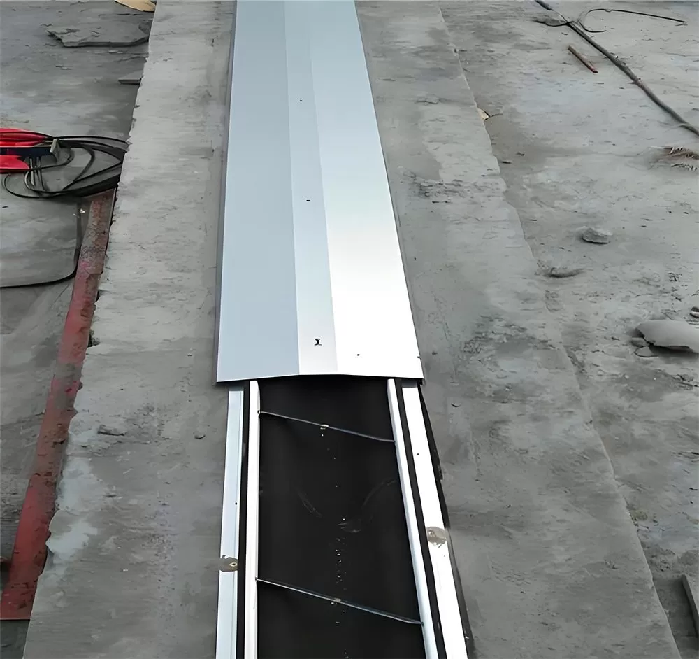
Step-by-Step Execution for Bridge Expansion Joint Replacement
Executing a successful joint replacement requires precise field procedures. Below is the typical sequence of operations required to achieve a durable installation.
Phase 1: Demolition and Concrete Removal
The existing joint and surrounding damaged concrete must be carefully removed. Hydro-demolition is the preferred method for this stage, as it selectively removes deteriorated concrete without micro-cracking the remaining sound structure. It also cleans rust from the existing reinforcing steel without damaging it, ensuring a strong bond with the new concrete headers.
Phase 2: Reinforcement and Steel Alignment
Once the joint cavity is clean, the new steel rails or modular assemblies are lowered into position. Proper elevation setting is critical; the top of the joint must be set 2 mm to 4 mm below the adjacent finished road surface to prevent damage from snowplows and minimize dynamic traffic impacts. The joint anchors are then welded or tied to the deck's primary structural reinforcement.
Phase 3: Pouring the Transition Headers
High-early-strength elastomeric concrete or rapid-setting polymer concrete is poured into the header forms. These materials cure quickly, allowing traffic to resume within a few hours, which minimizes lane closures and user delays. During this process, ensure the material is fully consolidated beneath the joint's steel flanges to prevent voids that could lead to early structural failures.
After the headers have cured, the primary elastomeric seal is installed using special lubricants and insertion tools, ensuring a continuous, tight fit along the entire width of the bridge deck.
Pre-Replacement Field Checklist
Before initiating field work, engineers and inspectors can use the following checklist to verify that all preparation steps are complete.
| Check | Item | Verification Protocol |
|---|---|---|
| Temperature Preset | Verify that the joint opening width has been adjusted for the ambient bridge temperature at the exact hour of installation, per design temperature curves. | |
| Substrate Integrity | Confirm that all micro-cracked and chloride-contaminated concrete has been removed from the header zone, exposing sound aggregate. | |
| Rebar Tie-in | Inspect all weld connections and tie-ins between the joint anchor loops and the bridge deck reinforcement for compliance with welding standards. | |
| Elevation Control | Use a straightedge to verify that the top of the joint steel rail is positioned 2–4 mm below the finished pavement surface on both sides. | |
| Drainage Outfall | Ensure the sub-joint drainage trough is correctly sloped and connected to the bridge's storm drainage system to prevent water pooling. |
Frequently Asked Questions (FAQ)
Can we use asphaltic plug joints for movements greater than 50 mm?
No. Asphaltic plug joints are generally limited to movements of ±25 mm or less. Attempting to use them for larger movements often leads to cohesive failure within the binder material, resulting in deep ruts, cracking, and eventual joint failure under heavy traffic loads.
What is the primary cause of premature failure in new joint headers?
The most common cause is poor consolidation of the concrete beneath the horizontal flanges of the joint's steel rails. If voids are left under these flanges during casting, the rail will flex slightly under heavy wheel loads, causing the surrounding concrete header to crack and spall within months of installation.
How does installation temperature affect the joint?
If a joint is installed and locked into place without adjusting for ambient temperature, it may fail prematurely. For example, if a joint is set too wide during hot weather, it will face excessive tension when the bridge contracts in winter, which can tear the elastomeric seal or pull the anchor studs out of the concrete.
Strategic Asset Management
Bridge expansion joint replacement is a critical maintenance task that directly impacts the long-term durability of a bridge's superstructure. By moving away from simple waterproofing quick-fixes and adopting systemic frameworks like the Joint Lifecycle Integrity Matrix (JLIM), asset managers can extend the service life of their bridges while reducing overall maintenance costs.
Using durable materials and robust designs from trusted manufacturers like KINGWORK ensures that replacement joints can withstand both heavy traffic and harsh weather. Implementing detailed field inspections and maintaining strict quality control during installation helps protect your infrastructure investments for decades to come.