How Do Structural Movements Influence the Durability of Bridge Expansion Joints?
Article content and related resources
Civil infrastructure requires meticulous engineering to withstand natural environmental cycles and dynamic loads. Bridges, in particular, are dynamic structures that expand, contract, and rotate in response to thermal fluctuations, concrete shrinkage, creep, and traffic-induced forces. Without adequate allowance for these movements, internal stresses would accumulate, leading to severe concrete spalling, structural misalignment, and eventual structural failure.
To prevent these issues, design engineers rely on specialized structural components positioned at strategic intervals along the bridge deck. These components accommodate multi-directional displacements while ensuring a continuous, smooth riding surface for vehicles. Achieving this balance requires an understanding of material science, structural dynamics, and manufacturing precision.
Mechanics of Structural Movement and Selection Criteria
The primary function of bridge expansion joints is to accommodate structural displacement without introducing stress concentrations into the bridge superstructure or substructure. Structural movement is not limited to a single plane; rather, it occurs in three dimensions. Thermal expansion causes longitudinal elongation, while wind loads and seismic forces induce lateral drift and rotational movements at the girder supports.
Calculating the total movement range is the first step in structural design. Engineers use specific formulas to estimate the anticipated displacement, factoring in the coefficient of thermal expansion of the structural materials, the span length, and the maximum temperature differential of the geographical location. Additionally, concrete structures undergo long-term deformations, such as shrinkage and creep, which permanently alter the baseline gap width over decades of operation.
Consequently, selecting the appropriate joint type depends on these calculated movement ranges. Small-span bridges with minimal movement require simpler configurations, whereas long-span structures, such as suspension or cable-stayed bridges, require complex modular systems capable of managing substantial multi-directional displacements. Improper selection can lead to premature failure, water ingress, and damage to the underlying bearings and piers.
Primary Typologies of Expansion Systems in Modern Infrastructure
Engineers categorize expansion systems based on their movement capacity, structural design, and sealing mechanisms. Each system serves specific span lengths and traffic conditions, offering distinct operational advantages.
Asphaltic Plug Joints
For small movement ranges, typically up to 50 millimeters, asphaltic plug joints provide a cost-effective and flexible solution. This system consists of a polymer-modified stone matrix asphalt poured over a metal bridging plate that spans the expansion gap. The material forms a continuous, seamless transition with the adjacent road surface, which minimizes traffic noise and prevents water penetration. Because of these characteristics, asphaltic plug joints are frequently used in urban environments where noise mitigation is a priority.
Compression and Strip Seal Joints
When movement demands increase up to 80 millimeters, strip seal or compression seal systems become necessary. A strip seal joint features a single, continuous elastomeric seal locked into two parallel steel edge profiles anchored directly into the bridge deck concrete. This design creates a watertight barrier, preventing debris and moisture from reaching the bridge substructure. The elastomeric profile can compress and stretch dynamically, maintaining its structural integrity under heavy wheel loads.
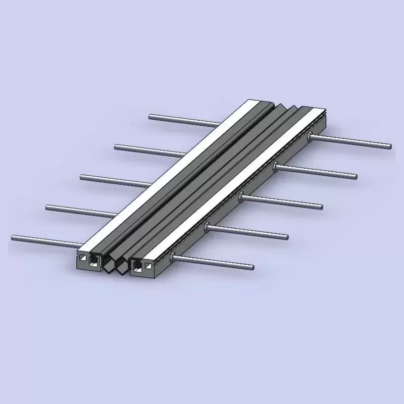
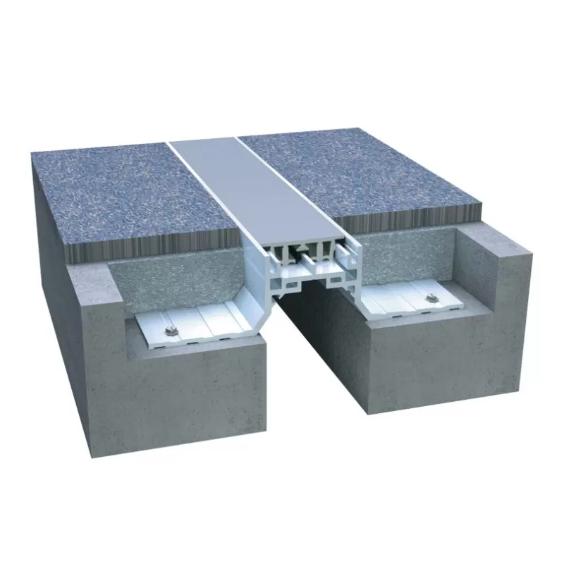
Modular Expansion Joints
For large-scale bridges with movement demands exceeding 80 millimeters, modular systems are the standard choice. These assemblies consist of multiple individual elastomeric seals separated by intermediate steel beams, known as center beams. The center beams are supported by transverse support bars that slide within control boxes embedded in the bridge deck. This arrangement distributes the total structural movement evenly across each individual seal gap, allowing the joint to accommodate longitudinal displacements of several meters, alongside transverse movements and vertical rotations.
Finger and Tooth Joints
Finger joints, also known as cantilevered tooth joints, are designed for medium to large movements where a completely sealed system is not the primary requirement, or where runoff water is managed via an under-joint drainage trough. These systems consist of interlocking steel plates shaped like fingers or teeth, anchored to the opposite sides of the expansion gap. This interlocking configuration provides a continuous support surface for vehicle tires, reducing impact loading and noise while allowing substantial longitudinal movement.
Structural Vulnerabilities and Engineering Challenges
The operational environment of a bridge deck is highly aggressive. Joints are subjected to millions of load cycles from heavy vehicle axles, exposure to deicing chemicals, extreme temperature swings, and UV radiation. Understanding the mechanisms of joint degradation is key to extending the service life of the entire bridge structure.
Water infiltration is a primary concern in bridge maintenance. When a seal fails, water laden with road salts penetrates the joint, flowing directly onto the underlying structural steel girders, concrete pier caps, and elastomeric bearings. This moisture initiates rapid corrosion of steel components and accelerates concrete carbonation, leading to structural degradation that is costly to remediate. For this reason, maintaining a watertight seal is a fundamental goal of modern joint design.
Mechanical fatigue represents another significant challenge. As heavy trucks pass over the joint, the impact loading generates high-frequency vibrations and dynamic stresses within the steel profiles and concrete anchoring systems. Over time, these cyclic forces can lead to weld fatigue, anchor bolt loosening, and concrete cracking in the transition zone. Addressing this requires robust structural designs, fatigue-resistant steel grades, and resilient elastomeric compounds manufactured by experienced suppliers like KINGWORK.
Material Selection and Quality Standards at KINGWORK
To withstand the demanding conditions of modern highway networks, the materials utilized in expansion joint manufacturing must adhere to strict quality parameters. KINGWORK implements rigorous material selection and fabrication processes to ensure long-term performance and reliability under diverse climatic conditions.
Structural Steel: Steel edge profiles and support bars are fabricated from high-yield structural steel, such as S355 or ASTM A709 Grade 50, providing high fatigue resistance and load-bearing capacity.
Elastomeric Elements: The sealing profiles are extruded from high-grade EPDM or Chloroprene (Neoprene) compounds. These elastomers exhibit resistance to ozone degradation, UV exposure, and oil contamination, retaining their elasticity in temperatures ranging from sub-zero winter conditions to intense summer heat.
Corrosion Protection: All exposed steel components undergo hot-dip galvanizing in accordance with ISO 1461 or are coated with multi-layer epoxy paint systems to prevent oxidation in marine or highly industrial environments.
Precision Machining: Advanced CNC cutting and robotic welding systems ensure that tolerances are kept within strict limits, ensuring smooth mechanical sliding and a precise fit during field assembly.
Installation Methodology and Quality Control
Even the most robustly engineered joint system will fail prematurely if installation is executed incorrectly. The installation process requires close coordination between the structural engineer, the contractor, and the manufacturer to ensure proper alignment and integration with the bridge deck.
Setting the initial gap width during installation is a delicate operation that must account for the ambient temperature of the bridge structure at the exact time of concrete pouring. If the bridge is warm and expanded during installation, the joint must be pre-set to a narrower gap; conversely, in cold conditions, the gap must be set wider. Failure to adjust for installation temperature can cause the joint to exceed its design limits during seasonal temperature extremes, leading to structural binding or seal pull-out.
Following correct positioning, the anchoring reinforcement must be welded securely to the bridge deck main reinforcement. The concrete poured in the block-out transition zone must be a high-strength, non-shrink mix, often fiber-reinforced, to withstand the localized impact forces of traffic. Proper curing of this concrete is vital before opening the structure to traffic to prevent micro-cracking and premature degradation of the transition zone.
Frequently Asked Questions
Q1: What is the average service life of a bridge expansion joint, and how can it be extended?
A1: The service life varies depending on the joint type and traffic volume. Typically, high-quality elastomeric seals last between 10 and 15 years, while the robust steel support structures of modular or finger joints can last 30 to 50 years. Extending this lifespan requires regular inspection, prompt debris removal, clearing of drainage troughs, and immediate replacement of damaged seals before water damages the internal structural steel components.
Q2: How do modular expansion joints accommodate movements in multiple directions?
A2: Modular systems utilize a series of individual gap seals separated by movable steel beams. These beams are supported by transverse support bars that slide within lubricated PTFE bearings inside joist boxes. This arrangement allows the entire assembly to translate longitudinally, slide transversely, and rotate slightly, distributing the overall movement evenly across each individual seal segment.
Q3: Can asphaltic plug joints be used on high-speed highways with heavy truck traffic?
A3: Asphaltic plug joints are suitable for small movement ranges, but their application on high-speed, heavy-vehicle lanes requires careful consideration. In areas with high volumes of heavy trucks or frequent braking, the asphaltic binder can undergo rutting or plastic deformation. For such conditions, a single-gap strip seal joint is often a more durable alternative.
Q4: Why is watertightness considered a primary design objective for expansion joints?
A4: Watertightness is vital because water passing through the joint carries dissolved oxygen, carbon dioxide, and deicing salts (chlorides). This corrosive mixture attacks the reinforced concrete piers, steel bearings, and structural abutments located beneath the deck. Preventing leakage is the most effective way to avoid expensive structural repairs to the bridge substructure.
Q5: What are the main causes of joint failure in the concrete transition zone?
A5: Failures in the transition zone are usually caused by inadequate concrete consolidation around the joint anchors, poor curing practices, or using standard concrete instead of high-strength, non-shrink grout. Additionally, high dynamic impact loads from heavy vehicles will quickly degrade weak or improperly anchored concrete, leading to spalling and joint looseness.
Project Engineering Consultation and Inquiry
Selecting the appropriate expansion system for a bridge project requires a balance of structural analysis, material science, and manufacturing expertise. At KINGWORK, our engineering team collaborates with structural designers and contractors worldwide to deliver custom-engineered solutions tailored to specific movement profiles, load requirements, and environmental conditions.
If you are currently designing, constructing, or rehabilitating a bridge structure and require detailed technical specifications, structural drawings, or budgetary estimates, please contact our engineering department. Submit your project requirements, including expected movement ranges, deck configurations, and loading parameters, and our specialists will provide a comprehensive proposal aligned with international engineering standards.