
How Do Bridge Pot Bearings Manage High Loads and Rotations in Modern Infrastructures?
Article content and related resources
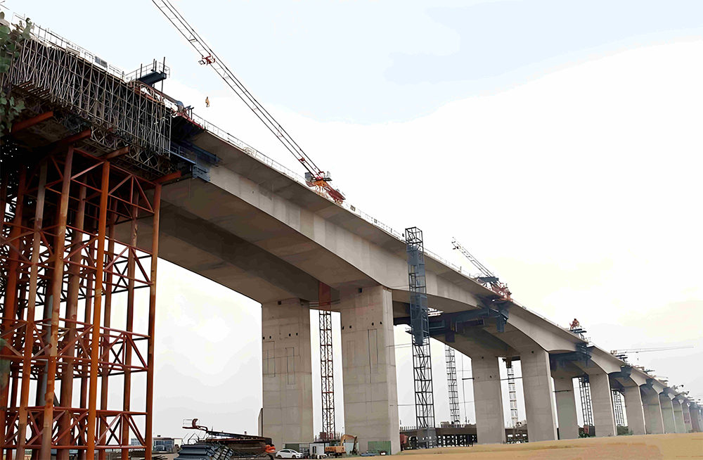
Modern civil engineering requires structural supports capable of handling complex load distributions, movements, and rotations. Elevated highways, long-span bridges, and high-speed rail viaducts must withstand dynamic and static forces while accommodating natural physical changes. These movements stem from temperature fluctuations, concrete creep, shrinkage, wind forces, and seismic activity. Without proper articulation points, these forces would induce immense stress within the superstructure and substructure, leading to premature cracking, structural distortion, or localized concrete crushing. Among the various structural components designed to manage these challenges, the bridge pot bearing stands out as a highly reliable solution for high-load applications.
A bridge pot bearing is a specialized structural device designed to transfer high vertical loads from the superstructure to the piers while permitting rotation about any horizontal axis. When configured as a sliding assembly, it also facilitates horizontal displacements in specified directions. Under the engineering and manufacturing standards of KINGWORK, these components are produced with high precision to verify that they satisfy international design criteria, providing long-term structural integrity for massive infrastructure projects.
The Physics and Working Principles of Confined Elastomers
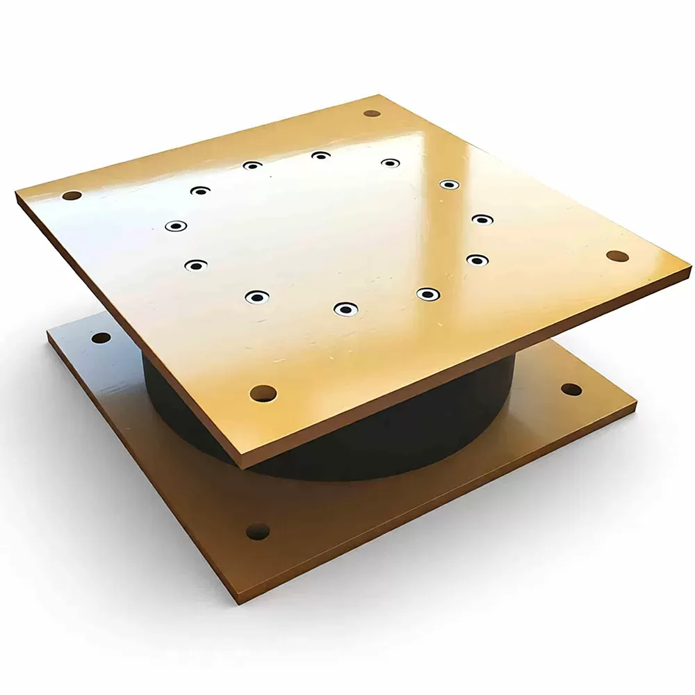
The mechanical efficiency of a bridge pot bearing relies on the physical behavior of a confined elastomer under high pressure. When an elastomeric pad is unconfined and subjected to compressive force, it bulges laterally. This lateral deformation limits the vertical load capacity of the elastomer because excessive shear stresses develop at the edges of the pad. The pot bearing overcomes this limitation by placing the elastomeric disc within a rigid, hollow steel cylinder, commonly referred to as the pot plate.
When the vertical load is applied via a tight-fitting steel piston, the elastomer is fully enclosed on all sides. Under high pressures, typically ranging from 25 to 40 MPa, the confined elastomeric material behaves like an incompressible, highly viscous fluid. It exhibits hydrostatic properties, distributing the applied load uniformly across the internal steel surfaces. This uniform pressure distribution allows the bearing to support loads that would destroy an unconfined elastomeric pad of similar dimensions.
Rotation is achieved through the internal shear deformation of the elastomeric disc. When the superstructure rotates due to traffic loading or deflection, the piston tilts slightly inside the pot. The elastomer deforms under shear to accommodate this change in angle. The resisting moment generated during this rotation is low, preventing the transmission of bending moments to the bridge piers. To maintain this fluid-like state, the elastomer must not escape from the confinement chamber. This requires a reliable sealing system to close the small gap between the piston and the inner wall of the steel pot.
Anatomy and Material Specifications of Pot Bearings
A standard bridge pot bearing consists of several precisely machined components, each chosen for its specific mechanical properties and durability. The interaction of these materials determines the overall performance and design life of the bearing assembly.
1. The Steel Pot and Piston
The steel pot is machined from a single piece of high-strength structural steel, such as S355JR or ASTM A709 Grade 50. Forging or machining from solid plate is preferred over welding to avoid weld-induced stresses and potential structural flaws. The inner chamber is machined to a smooth finish to reduce wear on the elastomeric pad and seals. The piston, which fits snugly into the pot, must possess high bending stiffness to distribute the vertical reactions uniformly without cupping or bowing under peak loads.
2. The Elastomeric Disc
The internal disc is made of natural rubber (polyisoprene) or chloroprene (neoprene) compounds. This elastomer must be formulated to resist physical aging, ozone exposure, and temperature extremes. It is designed to maintain its shear modulus and physical volume under continuous high-pressure conditions throughout its operating life.
3. Internal Sealing Rings
To prevent the elastomer from extruding through the clearance gap between the piston and the pot wall under hydrostatic pressure, sealing rings are installed. These seals must remain flexible while offering high resistance to wear and extrusion. KINGWORK utilizes multi-layered brass sealing rings or carbon-filled PTFE seals, which are seated in a recess along the perimeter of the elastomeric disc. These rings expand against the pot wall under pressure, maintaining a tight barrier even during dynamic rotations.
4. Sliding Interfaces
For sliding configurations, the top surface of the piston is recess-fitted with a dimpled polytetrafluoroethylene (PTFE) sheet. The dimples are filled with a specialized silicone grease that maintains its viscosity over a wide temperature range, minimizing the friction coefficient. Overlying this PTFE sheet is a polished stainless steel plate, typically Grade 316 or 304, finished to a mirror-like smoothness (roughness Ra < 0.2 microns). The contact between the polished stainless steel and the self-lubricating PTFE creates a low-friction sliding surface, permitting horizontal movement with minimal resistance.
Classification and Structural Configurations
Bridge designs dictate different movement requirements depending on the location of the bearing relative to the overall expansion scheme. Consequently, pot bearings are manufactured in three primary configurations to accommodate these varied engineering demands.
Fixed Pot Bearings: This configuration permits rotation about any horizontal axis but prevents horizontal movement in all directions. It acts as a structural anchor, transferring both vertical loads and horizontal forces (such as wind, braking, and seismic loads) directly to the substructure. It is typically positioned on key piers to define the thermal center of the bridge.
Guided Sliding Pot Bearings: These bearings allow rotation and horizontal movement along a single predefined axis. This uni-directional movement is achieved by incorporating robust steel guide bars on the sides of the sliding plate. These guide bars resist transverse horizontal forces while allowing the superstructure to expand or contract longitudinally.
Free Sliding Pot Bearings: Designed to permit rotation and multi-directional horizontal displacement, this type features a large sliding plate with no directional constraints. It is commonly used in wide or curved bridge decks where thermal movements occur in both longitudinal and transverse directions.
Structural Design Standards and Performance Metrics
The specification of a bridge pot bearing requires strict compliance with international design codes to verify safety, durability, and serviceability. Major design frameworks include EN 1337-5 (Structural Bearings - Pot Bearings) and the AASHTO LRFD Bridge Design Specifications. These standards govern the dimensional design, material testing, and structural calculation of the bearing assemblies.
The sizing of the elastomeric disc is determined by the maximum vertical design load under the Limit State Design philosophy. The average contact pressure on the elastomer is typically limited to a range of 30 to 40 MPa to prevent structural breakdown of the rubber matrix. The depth of the pot wall is calculated using elastic-plastic analysis to resist the lateral bursting pressure without undergoing permanent deformation. Additionally, the clearance gap between the piston and the pot must be carefully dimensioned to prevent steel-on-steel contact during maximum rotational deflection.
Rotational capacity is another parameter of interest, usually designed for up to 0.03 radians (approximately 1.7 degrees). The horizontal force capacity for fixed and guided bearings is calculated to resist braking loads from heavy trains or vehicles, wind loads, and centrifugal forces on curved structures. This horizontal resistance is transferred through the piston and pot walls, requiring precise calculation of shear and bending capacities in the steel sections.
Installation Methodologies and Quality Control
Even a well-designed bearing can experience premature wear or structural issues if installed incorrectly. The installation process demands meticulous planning, precise leveling, and correct alignment relative to the design axes of the bridge.
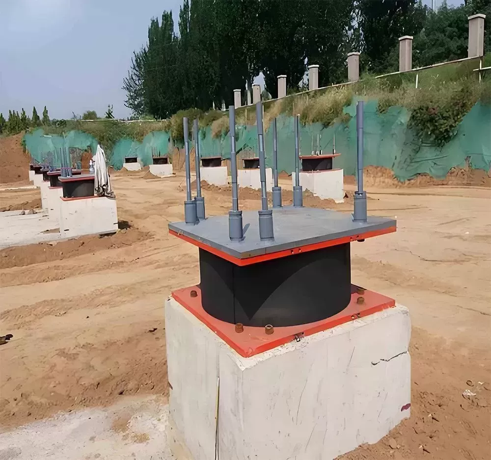
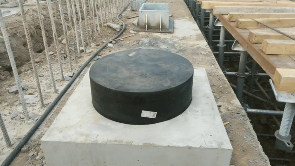
Prior to installation, the concrete bearing pedestals must be prepared. The surface of the pedestal is scabbled to remove laitance, cleaned of dust, and checked for flat tolerances. The bearing is placed on temporary leveling shims or adjusting screws to achieve the correct elevation and levelness, which is typically verified using precision dial gauges or laser levels. The deviation from horizontal is strictly limited, often to less than 1 in 1000, to prevent uneven loading and edge concentration on the internal elastomer.
Once aligned, high-strength, non-shrink cementitious or epoxy grout is poured underneath the base plate to create a uniform support bed. The anchor bolts, which secure the bearing to the pedestal, are tightened to the specified torque. For sliding bearings, temporary transit templates or transport brackets are installed by the manufacturer to keep the components aligned during shipping and concrete pouring. These brackets must be removed after the concrete deck has cured and before the bridge is subjected to its self-weight or construction traffic. Failure to remove these brackets restricts horizontal movement, which can cause severe distress to both the bearing and the concrete piers.
Durability Factors and Corrosion Protection
Bridges are exposed to harsh environments, including marine atmospheres, industrial pollution, de-icing salts, and temperature extremes. Because pot bearings are located in hard-to-access areas under the bridge deck, they must be designed for long-term durability with minimal maintenance.
Corrosion protection of the steel components is achieved through advanced coating systems. KINGWORK applies high-durability coatings, such as hot-dip galvanizing, thermal spray metallization (zinc-aluminum alloys), or multi-layer epoxy paint systems conforming to ISO 12944 standards for C5-I or C5-M high-corrosivity environments. The sliding surfaces must be kept free of dirt, grit, and construction debris. Rubber dust skirts or protective covers are installed around the sliding gap to shield the polished stainless steel and PTFE interfaces from dust accumulation, preserving the low coefficient of friction over decades of operation.
Frequently Asked Questions
Q1: What is the typical lifespan of a bridge pot bearing?
A1: Under normal operating conditions, regular maintenance, and proper installation, a high-quality pot bearing is designed to match the service life of the bridge superstructure, often exceeding 50 to 120 years. However, internal wear components such as the PTFE sliding sheets or elastomeric seals may require inspection and potential replacement after 30 to 50 years, depending on the dynamic traffic loading and environmental conditions.
Q2: How does temperature affect the friction coefficient of sliding pot bearings?
A2: The coefficient of friction of the PTFE-stainless steel interface increases at very low temperatures. At temperatures down to -40°C, the friction coefficient can double compared to its value at room temperature. Designers must account for this variation in their thermal load calculations to ensure the bridge substructure can resist the increased horizontal forces generated during cold weather movement.
Q3: Can pot bearings be used in seismic regions?
A3: Yes, they can be utilized in seismic zones, often in combination with other devices. While standard pot bearings accommodate thermal movements and standard traffic forces, they can be designed with heavy-duty steel shear keys to resist seismic shear forces, or paired with seismic dampers and isolators to dissipate energy during an earthquake.
Q4: How do pot bearings compare to spherical bearings?
A4: Pot bearings achieve rotation through the shear deformation of a confined elastomeric pad, making them highly efficient for moderate rotations (up to 0.03 radians) under high vertical loads. Spherical bearings achieve rotation through the sliding of a curved convex plate against a concave backing plate, accommodating much larger rotational angles (0.05 radians or more). Spherical bearings are often selected for highly flexible structures or curved bridges with complex rotational requirements, whereas pot bearings are generally more cost-effective for standard high-load structures.
Q5: What are the signs of bearing distress during routine bridge inspections?
A5: Inspectors should look for signs such as extrusion of the internal elastomeric pad around the piston gap, cracked or damaged brass sealing rings, deterioration of the corrosion protection coatings on steel parts, tearing or dislocation of dust skirts, uneven gaps between the piston and the pot, and build-up of debris on the sliding surfaces. Any unusual noise or vibration during traffic passage also warrants a detailed engineering evaluation.
Consult with KINGWORK for Your Infrastructure Projects
Selecting and designing the correct structural bearing requires deep technical expertise and an understanding of structural mechanics. At KINGWORK, our engineering team works closely with structural designers, consultants, and contractors to supply bridge pot bearings tailored to your specific project parameters. Whether you require standard configurations or customized designs to meet high load capacities or unique environmental challenges, we provide comprehensive support from initial calculations to manufacturing and delivery. Please contact our technical sales department to submit your design drawings, request load-capacity evaluations, or obtain a detailed project quotation.
![Bridge Joint Types: The Complete Engineering Guide [2026 Edition]](https://www.kwbridgebearing.com/storage/non_theme/202606/024.webp)