Bridge Joint Types: The Complete Engineering Guide [2026 Edition]
Article content and related resources
Bridges expand, contract, rotate, and displace under continuous environmental and traffic actions. Temperature swings, concrete creep, shrinkage, seismic events, and heavy vehicular live loads create constant structural movement. Without reliable mechanical joints, these internal stresses trigger deck cracking, bearing degradation, and catastrophic substructure failure.
Bridge expansion joints maintain continuous travel surfaces across deck openings while preventing runoff, deicing salts, and debris from penetrating substructure elements. Selecting the right joint assembly directly dictates long-term structural maintenance costs and service life.
For more than 13 years, KINGWORK has manufactured and supplied high-performance bridge components for critical infrastructure projects across 50 countries. This guide breaks down the core structural classifications, movement kinematics, and engineering selection criteria across all standard bridge joint types.
Planning a bridge construction or deck rehabilitation project? Contact KINGWORK today to submit your bridge displacement parameters, and our engineering team will deliver structural calculations and project-specific pricing within 24 hours.
Primary Bridge Joint Types: Engineering Classification and Mechanics
Structural engineers categorize bridge joint types primarily by their longitudinal movement capacity, structural geometry, and waterproofing mechanism. Selecting an incorrect category risks premature seal blowouts, anchor fatigue failures, or joint jamming.
1. Small Movement Joints (0 – 50 mm)
Small movement joints serve shorter spans, approach slabs, and footbridges where total thermal displacement remains below 50 mm.
Asphaltic Plug Joints (APJ)
An asphaltic plug joint is an in-situ flexible bridge expansion joint system. It consists of a specialized polymer-modified bitumen binder mixed with graded basalt aggregate, poured over an open gap bridged by a steel bridging plate.
- Movement Range: Typically ±25 mm longitudinal movement and ±6 mm vertical movement.
- Key Advantages: Seamless transitions with zero vehicular impact noise, rapid installation, continuous waterproofing, and cost-effective deck resurfacing.
- Engineering Limitations: Susceptible to rutting under slow, heavy-axle traffic in hot climates. Not suitable for curved bridges with substantial transverse shear displacements.
Compression Seal Joints
Compression seal systems use an extruded, multi-cellular neoprene (polychloroprene) elastomeric profile inserted directly into a preformed concrete or steel-armored joint gap.
- Movement Range: Typically 5 mm to 40 mm.
- Key Advantages: Simple mechanical installation, low initial procurement cost, and dependable performance under standard ambient conditions.
- Engineering Limitations: Relies entirely on continuous lateral compressive pressure against the joint walls. If joint openings widen past the seal's recovery limits, the profile loses wall contact, causing water infiltration.
2. Medium Movement Joints (50 – 100 mm)
Medium movement assemblies handle intermediate-span highway structures, elevated viaducts, and grade separations requiring robust mechanical anchoring.
Single Gap Strip Seal Joints
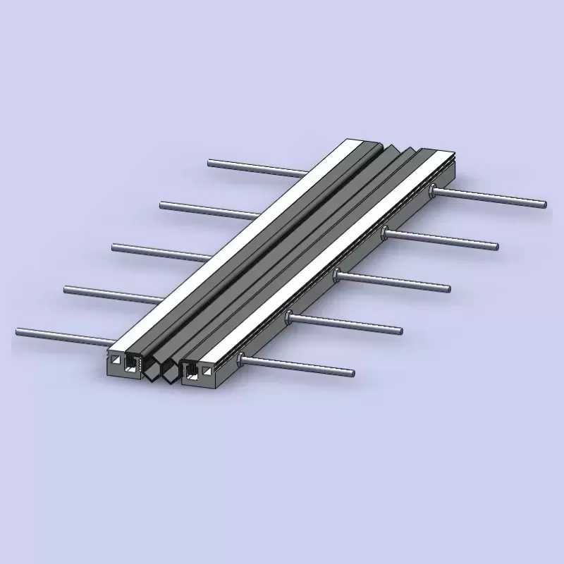
Strip seal joints represent the industry benchmark for medium spans. The system incorporates two heavy-duty rolled or extruded steel edge beams anchored into the bridge deck concrete, locking an elastomeric V- or W-shaped sealing element into specialized steel retainers.
- Movement Range: Standard capacity covers 0 to 100 mm of longitudinal translation.
- Mechanical Integrity: Edge profiles utilize structural steel (such as ASTM A709 Grade 50 or S355) with welded stud anchors that satisfy AASHTO Fatigue Limit State requirements.
- Waterproofing: The continuous EPDM or chloroprene gland forms a 100% watertight mechanical lock that prevents deck runoff from reaching structural bearings.
KINGWORK manufactures strip seal assemblies with high-durability hot-rolled edge profiles and ozone-resistant rubber glands. This configuration prevents seal expulsion under severe snowplow strikes and heavy wheel impact.
Elastomeric / Steel-Reinforced Rubber Expansion Joints
These joints comprise vulcanized synthetic rubber molded around load-distributing steel bridge plates. Anchored directly to concrete blockouts with high-tensile anchor bolts, the rubber blocks absorb movement via internal shear deformation.
- Movement Range: Typically 30 mm to 80 mm.
- Key Advantages: Cushions vehicular wheel loads, accommodates moderate structural skews, and dampens vibration transfer to bridge piers.
- Engineering Limitations: Rubber surface wear occurs over continuous heavy truck traffic, requiring periodic inspections of top cover plates and anchoring torque.
3. Large and Extreme Movement Joints (100 mm – 1200+ mm)
Long-span bridges, such as cable-stayed structures, suspension bridges, and large continuous concrete box girders, require systems capable of managing massive thermal translations and dynamic displacements.
Finger (Toothed) Expansion Joints
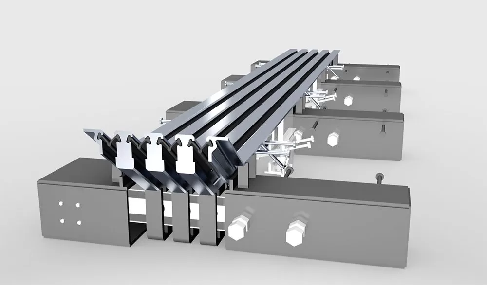
Finger joints bridge large deck gaps using cantilevered, interlocking steel teeth. These plates anchor directly to the main structural girders to transfer axle loads smoothly across the opening.
- Movement Range: 80 mm to over 400 mm.
- Structural Dynamics: The continuous tooth engagement eliminates impact shocks, reducing tire noise and vehicle bounce under heavy axle loads.
- Drainage Strategy: Finger joints are not naturally watertight. They require a heavy-duty reinforced rubber or stainless-steel drainage trough mounted directly beneath the teeth to collect and divert road contaminants away from the bearings.
Modular Expansion Joint Systems (MEJS)
Modular expansion joint systems represent the most sophisticated mechanical hardware applied to modern bridges. MEJS assemblies divide massive deck displacements into individual, watertight gaps using transverse center beams supported by longitudinal joist beams.
- Movement Range: Standard configurations accommodate 160 mm to 1200 mm, with custom systems handling movement beyond 2000 mm.
- Kinematic Controls: Polyurethane control springs and equidistant displacement mechanisms keep gap widths uniform during expansion and contraction cycles.
- Support Bar Configurations: Available in Single-Support Bar (swivel-joist) or Multiple-Support Bar systems to control dynamic load distribution.
KINGWORK builds modular expansion joints with fully penetrated, ultrasonic-tested welds and wear-resistant sliding components. Every production run undergoes complete mechanical dry-fit testing to confirm kinematic balance before site delivery.
4. Specialized Seismic Expansion Joints
Bridges in high-seismic zones require specialized joints capable of accommodating multi-directional dynamic displacements without catastrophic structural binding.
- Multi-Axis Kinematics: Designed to permit extreme longitudinal opening, transverse shear, and vertical seismic uplift.
- Fuse Mechanisms: Incorporates sacrificial pop-up panels or break-away plates that protect critical concrete edge beams from crushing during strong earthquakes.
- System Integration: Operates in coordination with Lead Rubber Bearings (LRB) and viscous dampers to maintain deck continuity after seismic events.
Bridge Joint Types Selection Matrix
Use this technical comparison matrix to evaluate movement ranges, typical applications, and maintenance demands across standard bridge joint types.
| Joint Classification | Movement Capacity | Applicable Bridge Spans | Watertight Performance | Maintenance Frequency | Typical Infrastructure Application |
|---|---|---|---|---|---|
| Asphaltic Plug Joint (APJ) | ≤ 50 mm (±25 mm) | Short spans (< 30 m) | High (Continuous seal) | Moderate (Resurfacing needed) | Urban overpasses, light rural bridges, low-speed routes |
| Compression Seal Joint | 5 mm – 40 mm | Short spans (< 40 m) | Moderate (Depends on pressure) | Moderate (Elasticity checks) | Precast concrete overpasses, parking viaducts |
| Single Gap Strip Seal | 50 mm – 100 mm | Medium spans (30 m – 90 m) | Exceptional (100% Watertight) | Low (Periodic gland cleaning) | Highways, urban flyovers, interstate bridges |
| Elastomeric Slab Joint | 30 mm – 80 mm | Medium spans (30 m – 70 m) | Good (Bolted clamping) | Moderate (Anchor bolt checks) | National highways, standard concrete box girders |
| Finger / Toothed Joint | 80 mm – 400 mm+ | Long spans (80 m – 250 m) | Requires Drainage Trough | Low to Moderate (Trough cleaning) | Heavy haul corridors, river crossings, marine bridges |
| Modular Expansion Joint | 100 mm – 1200 mm+ | Long to super-long spans (> 200 m) | Exceptional (Multiple seals) | Moderate (Sliding part inspection) | Cable-stayed, suspension, and multi-span continuous bridges |
Key Design Criteria for Bridge Joint Selection
Selecting an appropriate joint requires rigorous mechanical calculations. Structural designers must calculate dynamic deformations, environmental conditions, and long-term service loads.
1. Total Joint Movement Calculation
Engineers calculate total joint displacement using the following formula:
ΔL = L × α × ΔT + ΔLcreep + ΔLshrinkage + ΔLdynamic
- L: Effective expansion length of the bridge superstructure.
- α: Coefficient of thermal expansion of bridge materials (steel: ~12 × 10-6 / °C, concrete: ~10 × 10-6 / °C).
- ΔT: Design temperature differential between extreme thermal limits.
- ΔLcreep: Time-dependent shortening due to concrete creep.
- ΔLshrinkage: Long-term dimensional reduction from concrete curing shrinkage.
- ΔLdynamic: Live-load frame deflections, braking forces, and structural rotations.
2. Waterproofing and Bearing Protection
Joint leakage is the primary cause of bridge substructure degradation. Runoff containing deicing salts corrodes steel reinforcement, spalls concrete pier caps, and destroys expensive bridge bearings.
Specifying a continuous mechanical clamping seal, such as an EPDM or vulcanized neoprene gland, prevents moisture ingress. Joints with open designs (like finger joints) require dedicated, corrosion-resistant drainage troughs with positive fall angles to clear silt and debris.
3. Fatigue Limit State Design
Bridge expansion joints endure millions of dynamic wheel loading cycles over their design lifespans. Heavy axle impacts create severe stress concentrations on anchor studs, center beam welds, and support joists.
Modern specifications demand verification under AASHTO LRFD Bridge Design Specifications (Fatigue I and II limits) or European EN 1337-8 / ETAG 032 standards. All load-bearing welded joints must pass strict non-destructive testing (NDT) to prevent structural fatigue failures.
4. Acoustic Impact and Traffic Ride Quality
In urban residential zones, tire impacts over standard expansion gaps generate significant low-frequency noise. Selecting sinusoidal noise-dampening surface plates, asphaltic plug joints, or interlocking finger designs significantly lowers tire noise while minimizing vertical impact jolts on vehicular suspension systems.
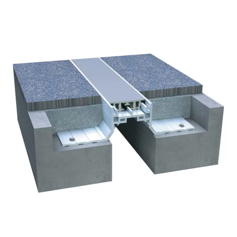
Manufacturing Specifications and Quality Control
Precision manufacturing guarantees bridge joint durability. Low-quality fabrication leads to premature anchor shear, weld cracking, and early water leakage.
At KINGWORK, manufacturing processes align with global structural fabrication standards:
- Standard Compliance: Fabricated to AASHTO LRFD, EN 1337, ETAG 032, and ISO 9001 quality benchmarks.
- Structural Metallurgy: Heavy hot-rolled steel profiles (S355JR, S355J2, or ASTM A709 Grade 50) paired with automated submerged-arc welding (SAW) and flux-cored arc welding (FCAW).
- Corrosion Protection: Hot-dip galvanization per ASTM A123 / EN ISO 1461, thermal spray metallization, or multi-coat epoxy systems engineered for marine and C5 industrial environments.
- Testing Protocols: 100% Non-Destructive Testing (UT and MPI) on critical welded connections, alongside tensile, ozone-resistance, and durometer verification for all rubber seals.
Frequently Asked Questions (FAQ)
Q1: What are the primary differences between modular expansion joints and finger joints?
A1: Modular expansion joints utilize multiple sealed gaps separated by steel center beams to absorb movement while maintaining a completely watertight deck barrier. Finger joints use cantilevered, interlocking steel plates that allow movement along a single plane. While finger joints handle heavy axle loads with minimal noise, they are not inherently watertight and require secondary drainage troughs underneath to handle deck drainage.
Q2: How do engineers determine whether to specify a strip seal or an asphaltic plug joint?
A2: The decision centers on movement range, traffic volume, and budget. Asphaltic plug joints serve short spans with movements under 50 mm, providing a smooth, quiet running surface at a lower initial cost. Strip seal joints suit medium-span movements (up to 100 mm), offer greater fatigue resistance under heavy freight traffic, and deliver a more reliable mechanical seal against water infiltration.
Q3: What causes premature failure in bridge expansion joints?
A3: The main causes include poor concrete consolidation in transition strip blockouts, dynamic fatigue from heavy wheel impacts, inadequate allowance for thermal movement during installation, and clogged drainage systems. Failure to clear abrasive road gravel from joint gaps accelerates rubber tearing and jams moving steel components.
Q4: How frequently should bridge expansion joint systems undergo inspection and maintenance?
A4: Routine visual inspections should occur every 6 to 12 months. Maintenance teams must inspect rubber gland retention, clear packed debris from seal valleys, check anchor bolt torque, and clean out sub-deck drainage troughs. Detailed structural and ultrasonic weld inspections are recommended every 2 to 5 years, depending on traffic volume.
Q5: Can standard bridge joint types accommodate skewed or curved structures?
A5: Yes, but skewed and curved decks generate both transverse and longitudinal movements. While simple strip seals can handle moderate skew angles (under 20°), highly skewed bridges require swivel-joist modular systems or custom-molded elastomeric expansion units engineered to manage combined multi-axis displacements without structural binding.
Engineering Support and Inquiries
Selecting the optimal system from various bridge joint types protects bridge substructures and optimizes capital investments. KINGWORK supplies certified, custom-engineered bridge expansion joint systems tailored to your specific project parameters, environmental exposures, and regional design codes.
Ready to finalize your bridge structural design or source joint hardware?
Contact our engineering support team directly. Submit your bridge movement schedules, structural drawings, or bill of quantities (BOQ), and KINGWORK will deliver comprehensive technical submittals, CAD details, and competitive commercial proposals within 24 hours.