Finger Joint Expansion for Bridge Decks: Engineering Principles and High-Cycle Performance
For bridges accommodating continuous traffic flow, thermal movements, creep, shrinkage, and seismic displacements demand robust deck joint systems. Among modular solutions, the finger joint expansion (also known as cantilever or comb joint) offers exceptional load transfer capacity, low noise emission, and durability under heavy axle loads. Unlike conventional compression seals or modular strip seals, finger joints eliminate elastomeric components that degrade under ultraviolet radiation and deicing chemicals. This technical analysis examines the mechanical rationale, metallurgical choices, installation protocols, and integration of finger joint expansion devices into modern bridge networks — with practical insights for civil engineers and infrastructure asset managers.
Leading infrastructure component manufacturers such as KINGWORK have refined the design parameters for these high-performance joints to extend service life beyond 30 years, even in corrosive environments or extreme temperature cycles. This article focuses exclusively on engineering-backed solutions for specifying, installing, and maintaining finger joint expansion systems in highway, railway, and pedestrian bridges.
1. Mechanistic Behaviour and Load Transfer Mechanism of Finger Joint Systems
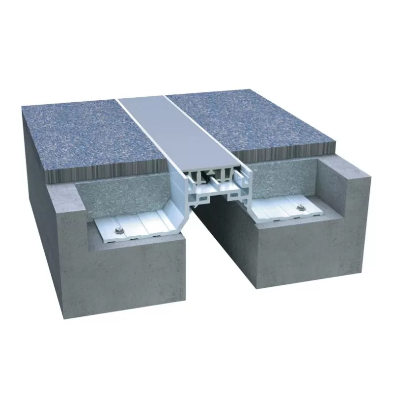
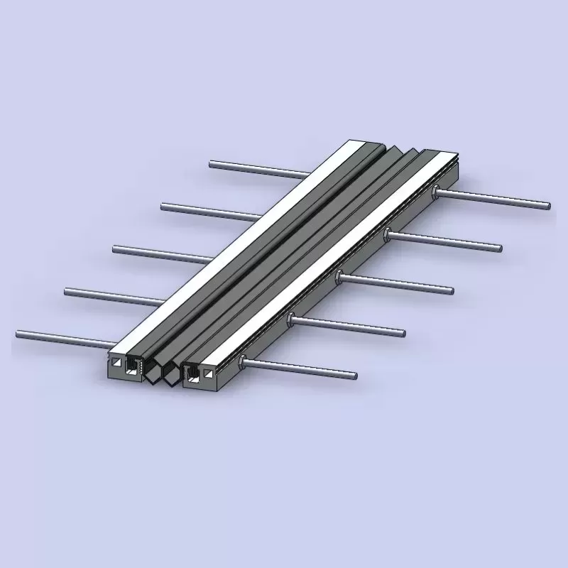
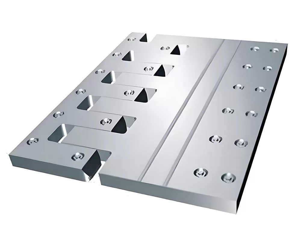
The operational principle of a finger joint expansion assembly relies on interdigitated steel plates that slide relative to each other while maintaining continuous surface contact for wheel loads. Each “finger” transfers vertical and horizontal forces directly to the supporting structural beam or anchoring system. Compared to modular expansion joints with drop-in bars, the finger joint expansion concept reduces impact loading because the gap between fingers remains small (typically 5–15 mm) even when the total expansion range reaches 400–800 mm in segmented configurations.
Key load transfer characteristics include:
Vertical stiffness: The finger thickness (commonly 25–50 mm) and root geometry determine deflection under design wheel loads (e.g., HL-93 or LM1). Minimizing differential deflection between adjacent fingers prevents edge loading and local fatigue.
Longitudinal sliding resistance: Friction coefficients between sliding surfaces (hardened steel-on-steel or steel-on-PTFE) directly affect combined movement forces on substructures. Typical values range from μ = 0.10 to 0.15.
Transverse shear distribution: Oblique finger orientations (e.g., 60° or 70° relative to the traffic axis) facilitate multi-axis movement for skew bridges and curved alignments.
For large displacement applications, multi-member finger joint expansion blocks can be arranged in parallel, each handling a specific movement range. This modularity allows engineers to replace individual segments without full deck closure — a significant operational advantage for high-traffic bridges.
2. Critical Design Parameters for High-Performance Finger Joint Expansion Devices
Proper sizing and specification require rigorous analysis of site-specific demands. Below are the primary engineering inputs when designing a finger joint expansion system:
2.1 Movement Range and Finger Geometry
The total required movement (Δtotal) determines the maximum gap opening. For finger joint expansion systems, the cantilever length of each finger must be at least twice the maximum displacement plus safety margins. Typical ratios: L_finger = 2.5 × Δmax. The root-to-tip thickness taper controls bending stress. Finite element analyses should verify that maximum von Mises stresses remain below 70% of the steel’s yield strength at extreme gap openings.
2.2 Fatigue Resistance Under High-Cycle Traffic Loading
Bridges in urban corridors experience millions of load cycles annually. Finger joint expansion assemblies must pass fatigue tests per AASHTO LRFD or EN 1993-6. Critical fatigue details include finger root welds, anchoring stud connections, and the sliding interface. Design practices such as avoiding weld terminations at high-stress concentration zones and using full-penetration butt welds dramatically improve fatigue life. Laboratory data show that properly designed finger joint expansion units exceed 2 million cycles at 330 kN wheel load without crack initiation.
2.3 Waterproofing and Drainage Integration
Uncontrolled water leakage through expansion joints accelerates corrosion of substructures and bearings. Modern finger joint expansion systems include an elastomeric membrane or a stainless-steel drip pan below the sliding fingers. Additionally, edge drains should be placed at the lowest point of the joint trough to remove deicing salts. For bridges with high environmental exposure, closed-cell foam seals can be compressed between finger gaps, providing a secondary water barrier without affecting movement capacity.
3. Material Selection and Corrosion Protection Strategies
The durability of a finger joint expansion largely depends on material choices and surface protection. Two predominant grades are used globally:
Structural steel S355J2+N or S460N: Suitable for moderate climates with regular inspection. Protective coatings (zinc-rich primer + polyurethane topcoat) of 320–400 μm DFT are mandatory.
Hot-dip galvanized steel + duplex coating: For deicing salt exposure or coastal bridges, min. 85 μm zinc layer followed by 120 μm epoxy coating improves salt spray resistance to >5,000 hours (ISO 12944 C5-M).
Stainless steel grades (1.4462 duplex or 1.4404): Required for pedestrian bridges, architectural applications, or where maintenance access is severely limited. Although higher initial cost, they eliminate coating lifecycle expenses.
KINGWORK recommends customized material certifications and surface treatment documentation for each project, ensuring full traceability. For concrete-embedded anchor systems, hot-dip galvanized or stainless-steel anchor bars are non-negotiable to prevent crevice corrosion at the interface. Proper coating repair procedures for on-site welding must be defined in the installation manual.
4. Installation Best Practices and Quality Assurance
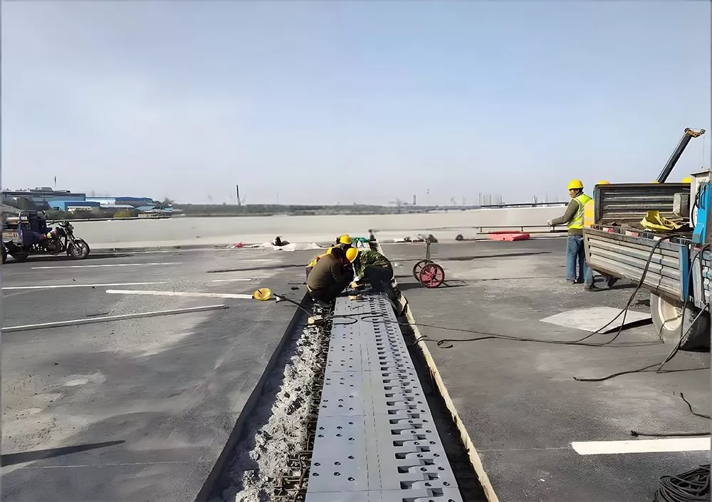
Incorrect installation remains the primary cause of premature finger joint expansion failure. Contractors must adhere to the following sequence:
Chamber preparation: The expansion gap recess in the deck must be cut precisely, with reinforcement bars repositioned to avoid interfering with anchor channels. Concrete compressive strength at installation time should exceed 80% of design strength.
Temporary support and alignment: The finger joint expansion assembly is set at the specified ambient temperature using spacers to pre-set the initial gap. If installed at extreme temperatures, movement capability reduces linearly — engineers must calculate the installation gap equation Δset = (α × L × (Tset - Tmin)).
Concrete casting and consolidation: High-performance non-shrink grout (≥ 60 MPa) is pumped under the joint frame. Vibration must avoid displacing fingers. Curing for a minimum of 7 days or until compressive strength reaches 50 MPa before opening to traffic.
Final clearance check: Feeler gauges verify that no parasitic contact exists between finger sides over the entire movement range. Grout excess removal and application of a protective coating on all exposed anchoring bolts.
Post-installation acceptance testing for a finger joint expansion typically includes movement cycle verification (manually actuated jacks) and dye penetrant inspection of critical welds. Documentation of as-built gaps and ambient temperature is required for warranty validation.
5. Integration with Seismic Isolation and Bearing Systems
In high-seismic regions, finger joint expansion units must accommodate not only thermal movements but also earthquake-induced displacements, including transverse and vertical components. While the joint itself does not dissipate seismic energy, its movement capacity must coordinate with isolators (e.g., lead rubber bearings or friction pendulum bearings).
Key seismic design considerations:
Design displacement check: At maximum considered earthquake (MCE), the finger joint expansion’s total stroke shall not be exceeded. If thermal range is 100 mm, seismic demand adds another 150–250 mm — requiring either larger finger geometry or a secondary overlapping plate arrangement.
Stopper and restrainer systems: Some applications integrate sacrificial shear pins or elastomeric bumpers that engage beyond service movements, preventing unseating while allowing finger joint expansion rotation.
Vertical acceleration capacity: During vertical seismic motion, finger contact forces may exceed static values. Dynamic load factors of 1.8–2.0 are applied to component design. Anchor bolts should be designed for tension and shear interaction according to ACI 318 Appendix D.
KINGWORK’s engineering support includes non-linear time-history analysis compatibility check for the finger joint expansion within the global bridge model. This ensures that the joint’s mechanical stopper system does not become a restraining point that alters seismic load paths to piers.
6. Common Failure Modes and Predictive Maintenance
Despite robust design, finger joint expansion assemblies can exhibit specific distress patterns after decades of service. Recognizing early signs allows cost-effective rehabilitation:
Finger tip curling or permanent set: Results from overload events (e.g., heavy truck overloading) or inadequate root thickness. Laser scanning of the joint profile every 3 years quantifies residual deformation.
Wear of sliding bearing pads: If the finger joint expansion uses PTFE or bronze sliding plates beneath the finger tips, periodic thickness measurements are required. Replacement intervals vary from 15 to 25 years depending on traffic volume.
Anchor bolt loosening: Cyclic impact causes nut back-off. Use of double nuts, locking inserts, or torque-controlled shear-off bolts eliminates this issue.
Debris accumulation and corrosion: Rubber wheel scrubbing deposits debris in finger gaps; annual cleaning with pressurized water prevents salt retention. Non-destructive coating thickness gauges verify remaining protection.
Predictive maintenance strategies incorporate annual visual inspections, dynamic deflection measurements under test trucks, and acoustic monitoring of impact noise. Replacement of individual fingers or wearing plates can be executed during weekend closures without replacing the whole finger joint expansion unit, reducing lifecycle cost and traffic disruption — a key advantage over seal-type joints.
7. Frequently Asked Questions about Finger Joint Expansion
Q1: What is the maximum movement range of a standard finger joint
expansion system?
A1: Single-module finger joint
expansion units accommodate movements up to 400 mm (total range). For larger
displacements up to 800 mm or more, multiple overlapping finger bars or a
combined sliding-finger configuration is used. The exact capacity depends on
finger cantilever length, steel grade, and supporting beam stiffness. Custom
designs from manufacturers like KINGWORK can exceed 1000 mm for special
long-span bridges.
Q2: How does a finger joint expansion differ from a modular expansion
joint (MEJ) with support bars?
A2: MEJ systems
typically use multiple rubber seals and center beams for large movements but
require deeper deck recesses (up to 500 mm) and are prone to noise and rubber
extrusion. Finger joint expansion units have a shallower embedment depth
(150–300 mm), produce lower rolling noise because of continuous steel surface
contact, and allow easier replacement of individual components. However, finger
joints require higher precision in fabrication to ensure even load sharing among
fingers.
Q3: What types of bridges are most suitable for finger joint
expansion adoption?
A3: Steel and concrete girder
bridges with movements exceeding 100 mm, skew bridges (because finger geometry
can be oriented to match skew angle), curved viaducts, and heavily trafficked
urban viaducts where low noise and low maintenance are priorities. They are also
specified for airports’ apron bridges and railroad underpasses where seal
deterioration would cause rapid track degradation.
Q4: Can a finger joint expansion be retrofitted into an existing
bridge with a failed compression seal?
A4: Yes,
retrofit is feasible but requires careful evaluation of the existing recess
dimensions and anchor zones. Typically, the old joint is removed, concrete
surfaces are prepared, and a new deeper support beam or steel frame is cast to
accommodate the finger joint expansion assembly. The deck’s longitudinal
reinforcement must be verified to provide sufficient pull-out resistance for the
new anchor bolts. Silane-treated interfaces prevent spalling at the
concrete-steel boundary.
Q5: How is waterproofing ensured at the interface between the finger
joint expansion and the deck surface?
A5: A
continuous 2.0 mm to 3.0 mm thick EPDM or chloroprene membrane is clamped
between the joint frame and the deck. The membrane extends at least 300 mm
beyond both edges of the joint opening. Additionally, a gutter plate with a
downward slope of 2% directs any infiltrated water to a bridge scupper. For
aggressive environments, a double sealing system (primary compression gasket
under fingers plus secondary membrane) is recommended.
Q6: What fatigue test standards apply to finger joint expansion
components?
A6: For North American projects, AASHTO
M 242 (Modular Expansion Joints) with 2 million cycles at 60% or 80% of design
load is common, though specific finger joint protocols follow NCHRP Report 402.
European projects adhere to EN 1337-3 (for bearings) combined with EN 1993-6 for
fatigue class details. Independent testing should validate that no crack exceeds
0.5 mm after service life simulation.
Engineered Reliability for Bridge Infrastructures: Partner with KINGWORK
Selecting the right finger joint expansion system demands both application-specific engineering and proven manufacturing quality. KINGWORK provides full-cycle technical support — from movement analysis and custom finger geometry design to shop drawing approval and on-site installation training. Our finger joint expansion products are fabricated in ISO 9001:2015 and ISO 3834-2 certified facilities, with material test certificates (EN 10204 3.2) provided for every project. Whether your bridge requires seismic accommodation, corrosion-resistant stainless steel finishes, or extended fatigue life, KINGWORK’s engineering team delivers tailored solutions that minimize future maintenance burdens.
For spec sheets, load-rating calculations, or a dedicated consultation on finger joint expansion specifications for your upcoming bridge project, contact KINGWORK’s B2B technical desk directly. Our infrastructure specialists provide displacement capacity plots, installation sequencing drawings, and lifecycle cost comparisons based on actual traffic data. Request your technical proposal and ensure your bridge expansion joints perform under every service condition.
Contact KINGWORK now for a comprehensive finger joint expansion engineering review – send your bridge parameters and movement requirements to our engineering support team.