
Engineering Continuity: Design and Execution of Construction Joints in Bridges
Article content and related resources
 (1).webp)
In large-scale concrete infrastructure, pouring an entire structure in a single continuous operation is rarely feasible due to limitations in concrete supply, formwork capacity, labor shifts, and thermal heat dissipation. Consequently, the correct execution of construction joints in bridges remains a primary factor in preventing premature structural deterioration and ensuring long-term load-bearing capacity.
Unlike expansion joints, which are designed to accommodate thermal and structural movement, a construction joint is a planned interruption in the concrete casting process where structural continuity must be fully maintained. This analysis examines the engineering principles, placement strategies, execution protocols, and maintenance methodologies necessary to achieve durable construction joints in modern bridge engineering.
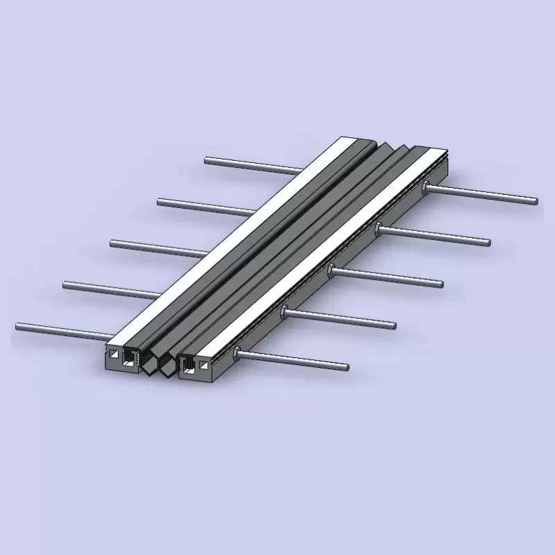
The Engineering Necessity of Joint Placement
Placing construction joints in bridges at structural locations of minimum shear is a fundamental rule of structural design. The location must be carefully calculated during the engineering phase to prevent compromising the structural capacity of the concrete member.
Shear and Bending Moment Considerations
For simple span beams and slabs, the bending moment is highest at the mid-span, while the shear force is highest near the supports. Consequently, vertical construction joints in the superstructure are typically placed within the middle third of the span, where shear forces are relatively low. In continuous structures, the location of the inflection points—where the bending moment changes sign and is theoretically zero—presents another potential location for joint placement, provided shear reinforcement is designed accordingly.
Thermal and Shrinkage Stresses
As concrete cures, it undergoes hydration heat dissipation and drying shrinkage. If the pour volume is too large, the restraint of these volume changes induces high tensile stresses, leading to macro-cracking. By introducing planned construction joints, engineers can segment the pour into manageable volumes, allowing initial shrinkage to occur in sections before the adjacent concrete is cast. For complex major structures, collaborating with experienced structural solution providers like KINGWORK can assist in ensuring that joint detailing aligns with the thermal movement strategy of the overall design.
Types of Construction Joints and Their Structural Mechanics
Depending on the orientation of the pour and the structural requirements of the bridge component, several joint configurations are utilized. Each type relies on different mechanisms to transfer loads across the cold joint interface.
1. Plain Butt Joints
A plain butt joint is the simplest configuration, where the new concrete is cast directly against a cured, flat concrete surface. This joint relies entirely on the bond strength between the two concrete layers and the reinforcing steel crossing the interface to transfer shear and tensile forces. Because it offers minimal mechanical interlock, its use is generally restricted to areas with very low structural shear demands.
2. Keyed Joints
Keyed joints incorporate a tongue-and-groove profile cast into the first concrete pour. When the second pour is completed, the concrete fills the keyway, creating a mechanical interlock. This design significantly improves the shear transfer capacity across the joint.
Design Parameters: The keyway depth is typically 1/4 to 1/3 of the member thickness.
Limitations: If not reinforced correctly, the concrete keys can suffer from localized shear failure or spalling during structural loading.
3. Doweled Joints
In high-load applications, reinforcing steel dowels or continuous reinforcement bars must cross the joint interface to handle tensile and shear forces. The shear-friction theory, outlined in codes such as AASHTO LRFD and Eurocode 2, governs this design. The reinforcing steel crossing the joint is designed to resist the tension forces generated by shear sliding along the joint plane, forcing the two concrete surfaces together and increasing frictional resistance.
Key Challenges and Structural Vulnerabilities
Unprofessional design or poor execution of construction joints can lead to serious structural defects that shorten the service life of a bridge.
Water Ingress and Reinforcement Corrosion
The interface of a construction joint is naturally a plane of weakness. If the joint is not dense and properly bonded, water containing deicing salts (chlorides) can penetrate the joint. This moisture migration leads to the carbonation of the concrete and the corrosion of the internal reinforcing steel. Once corrosion begins, the resulting volumetric expansion of the steel causes concrete spalling and structural degradation.
Laitance and Poor Adhesion
During the placing and vibration of concrete, excess water and fine cement particles rise to the surface, forming a weak, porous layer known as laitance. If this laitance is not thoroughly removed before the subsequent concrete pour, it acts as a bond breaker, preventing the new concrete from adhering to the aggregate of the previous pour. This results in a weak plane susceptible to shear sliding and water leakage.
Cold Joints
A cold joint occurs when a delay in concrete delivery or placement causes the initial concrete pour to begin setting before the next layer is placed. Unlike planned construction joints, cold joints occur accidentally and lack the necessary reinforcement detailing or surface preparation, creating severe structural vulnerabilities in the bridge element.
Best Practices in Joint Preparation and Execution
To ensure structural performance, rigorous execution protocols must be followed on-site. The preparation of the joint interface determines the bond strength and overall durability of the connection.
Surface Retarders and Mechanical Roughening
To achieve a high-bond interface, the surface of the cured concrete must be roughened to expose the coarse aggregate without fracturing it. Two primary methods are utilized:
Chemical Surface Retarders: Applied to the formwork or the exposed surface of the first pour. This retards the set of the surface cement paste, allowing it to be easily washed away with high-pressure water jetting once the bulk concrete has cured.
Mechanical Roughening: Sandblasting, shot-blasting, or scabbling of the hardened concrete surface to achieve a minimum amplitude roughness of 6 mm (as specified by many highway authorities).
Moisture Conditioning
Before placing the new concrete, the existing concrete surface must be brought to a saturated-surface-dry (SSD) condition. If the old concrete is dry, it will absorb water from the freshly mixed concrete, preventing proper hydration of the cement paste at the joint interface and resulting in a weak, powdery bond. Conversely, standing water on the joint surface must be avoided, as it increases the local water-cement ratio and reduces concrete strength.
Waterproofing and Joint Sealants
For joints exposed to weather or hydrostatic pressure, such as in abutments or deck slabs, additional waterproofing is required. High-performance swelling waterstops or joint systems engineered by specialized firms such as KINGWORK can be integrated into the construction sequence to prevent moisture transmission through the concrete interface.
Distinguishing Construction Joints from Other Bridge Joint Types
To avoid structural detailing errors, it is necessary to clearly distinguish construction joints from other joint types used in bridge engineering.
| Joint Type | Primary Function | Structural Continuity | Reinforcement Status |
|---|---|---|---|
| Construction Joint | Facilitate concrete pouring phases and control initial shrinkage stresses. | Fully Continuous (designed to transfer all loads). | Continuous reinforcement and dowels cross the interface. |
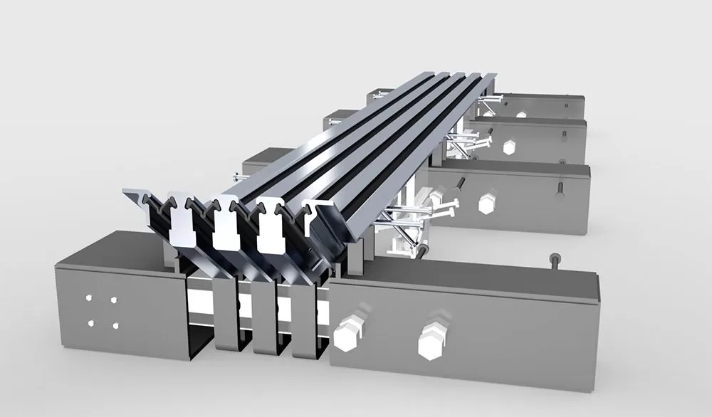
| Expansion Joint | Accommodate thermal expansion, contraction, and seismic movements. | Discontinuous (allows movement between spans). | No continuous reinforcement crosses the gap; utilizes mechanical expansion joint systems. |
| Contraction Joint | Control location of shrinkage cracking in thin, non-structural elements. | Partial Continuity (limits tensile stress transfer). | Reinforcement is often reduced or doweled to allow controlled opening. |
While expansion joints are designed to accommodate continuous displacement, construction joints in bridges are intended to maintain complete structural continuity, behaving as if the concrete were cast in a single monolithic pour.
Inspection, Quality Control, and Rehabilitation
Long-term maintenance requires routine inspections to confirm that construction joints continue to perform as designed without leakage or structural distress.
Non-Destructive Testing (NDT)
Structural engineers utilize several non-destructive evaluation techniques to assess the integrity of joint interfaces:
Ultrasonic Pulse Velocity (UPV): Measures the speed of acoustic waves passing through the joint. Voids or poor bonding will slow the wave speed, identifying internal defects.
Impact-Echo Testing: Detects delamination or cracking along the joint interface by analyzing stress wave reflections.
Ground Penetrating Radar (GPR): Used to verify reinforcement placement, concrete cover, and detect moisture ingress patterns around the joint area.
Remedial Grouting and Repair
If a construction joint begins to leak or shows signs of minor separation, remedial actions should be taken promptly to prevent structural damage.
Epoxy Injection: High-modulus structural epoxies can be injected under pressure into non-moving cracks or debonded joint interfaces to restore structural bond and shear transfer capability.
Polyurethane Grouting: For joints experiencing water seepage without structural failure, hydrophobic polyurethane grouts can be injected. The grout reacts with the moisture, expanding to form a flexible, watertight seal within the joint void.
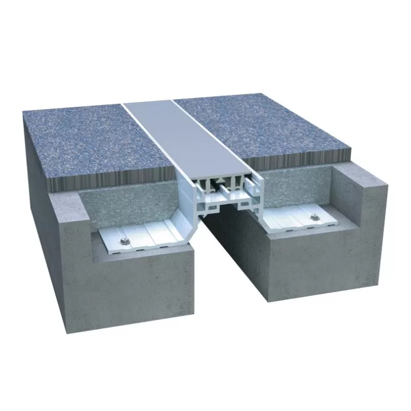
Structural Integration with Bearings and Expansion Joint Systems
The placement and design of construction joints must be coordinated with the positioning of bridge bearings and expansion joint installations. Properly detailed construction joints in bridges transfer loads smoothly to the bearings and substructure without generating localized stress concentrations.
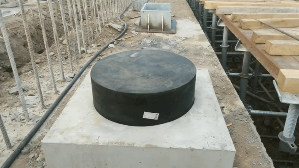
When concrete spans are cast in sections, the sequential loading can cause rotational movements at the pier caps. If the construction joint sequence is not managed, it can induce eccentric loads on elastomeric bearings. Modern integrated bearing, expansion joint, and structural systems from KINGWORK are engineered to withstand these complex installation phases, ensuring that structural loads are distributed in accordance with the design assumptions.
In conclusion, the proper engineering and treatment of construction joints in bridges are vital to ensuring the long-term load-bearing capacity of the concrete structure. Successful execution relies on placing joints in low-stress zones, preparing the concrete interface to expose the aggregate, maintaining continuous reinforcement, and incorporating reliable waterstop systems. By adhering to these structural guidelines and utilizing qualified components, engineers can mitigate the risks of water ingress and reinforcement corrosion, securing the long-term durability of the transportation infrastructure.
Inquiry and Technical Support
For complex bridge designs,
selecting the right waterproofing systems, structural bearings, and expansion
joint accessories is highly important. Contact the engineering advisory team at
KINGWORK to obtain custom solutions, design drawings, and support for your
current or upcoming infrastructure projects.
Frequently Asked Questions
Q1: Why is it necessary to remove concrete laitance at a construction
joint?
A1: Laitance is a weak, porous layer consisting of water,
cement, and fine aggregates that rises to the top of curing concrete. If left in
place, it prevents the subsequent concrete pour from forming a strong
aggregate-to-paste bond with the existing layer, resulting in a structural weak
plane highly susceptible to shear failure and water penetration.
Q2: Can a construction joint be placed anywhere if sufficient
reinforcement is provided?
A2: No. While reinforcement helps
transfer tensile and shear forces, construction joints should always be placed
in zones of minimum shear stress and bending moments, typically within the
middle third of the span for slabs or beams, to minimize structural risk and
ensure redundancy.
Q3: What is the purpose of a saturated-surface-dry (SSD) condition
before casting new concrete?
A3: An SSD condition ensures that the
cured concrete surface is saturated with water but has no standing water on top.
This prevents the dry concrete from absorbing water from the fresh concrete mix,
which would otherwise starve the hydration process at the interface and weaken
the bond.
Q4: How does a keyway improve the shear capacity of a construction
joint?
A4: A keyway creates a mechanical interlocking key between
the two concrete pours. When shear forces are applied parallel to the joint, the
concrete tongue resists the movement through direct bearing and shear
resistance, reducing the reliance on pure friction and steel reinforcement
alone.
Q5: What is the difference between a cold joint and a planned
construction joint?
A5: A planned construction joint is a designed,
prepared interface where the pour is intentionally stopped, containing specific
structural details such as keys, waterstops, and continuous reinforcement. A
cold joint is an unplanned defect that occurs when concrete pouring is delayed,
causing the new concrete to be placed against already hardened concrete without
proper surface preparation or structural detailing.
![Bridge Joint Types: The Complete Engineering Guide [2026 Edition]](https://www.kwbridgebearing.com/storage/non_theme/202606/024.webp)