Concrete Deck Expansion Joint: Load Transfer, Watertight Sealing & Service Life
In modern bridge engineering and highway infrastructure, the interface between prefabricated girders, cast-in-place slabs, and approach slabs creates inevitable movement. A properly designed concrete deck expansion joint is not an accessory—it is a structural articulation that accommodates thermal expansion, concrete creep, shrinkage, and vehicle-induced dynamic displacements. Poor selection or faulty installation of these joints leads to spalled edges, leaking water onto substructures, accelerated corrosion of reinforcement, and unplanned lane closures. This article provides a deep-dive into design philosophies, material science, load transfer mechanisms, and field-proven maintenance strategies for bridge deck expansion joints, with engineering data derived from global heavy-haul and high-cycle fatigue environments.
1. Functional Demands of Modern Deck Expansion Joints
Unlike simple building expansion joints, bridge deck joints endure direct wheel loads, impact, deicing salts, and large seasonal movements. The core functional requirements for any concrete deck expansion joint system include:
Load transfer continuity: The joint must transmit vertical shear and longitudinal forces from one deck edge to the adjacent edge without differential deflection that damages the wearing surface.
Watertight integrity: Leakage through joints causes girder end corrosion, bearing deterioration, and freeze-thaw damage in colder climates.
Movement accommodation: Ranges from ±6 mm for small modular strip seals to over ±200 mm for large modular finger joints or sliding plate systems.
Surface evenness: Step-height differences at the joint generate impact loads up to three times the static wheel load, quickly degrading the joint assembly and adjacent concrete.
Durability against chlorides and abrasion: Winter maintenance introduces chloride-based deicers that accelerate corrosion of embedded steel components if seals fail.
Field studies from North American and European highway agencies indicate that over 40% of bridge rehabilitation costs are linked to failed or underperforming deck joints. Consequently, specifying the correct joint type based on movement capacity, traffic volume, and exposure class is a primary responsibility of bridge engineers.
2. Classification of Concrete Deck Expansion Joint Systems
2.1 Buried Joints (Asphaltic Plug Joints)
These are economical for very small movements (≤20 mm) and low-traffic rural bridges. The joint is filled with a polymer-modified asphalt mixture compacted into a gap. However, they exhibit poor fatigue resistance under heavy goods vehicle loading – rutting and extrusion typically appear within 3–5 years. Not recommended for highways with Annual Average Daily Truck Traffic (AADTT) above 2,000.
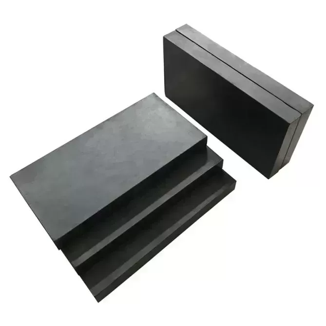
2.2 Compression Seal Joints
Preformed neoprene or silicone seals are compressed into a steel-reinforced gap. Effective for movements up to 40 mm. The seal provides watertightness but requires precise edge preparation. Chloride intrusion often occurs at the seal-concrete interface if the joint faces are not sealed with a compatible epoxy adhesive. These joints are widely used in bridge decks with moderate skew angles.
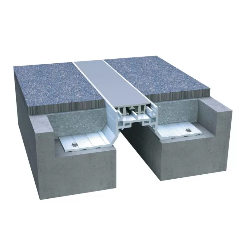
2.3 Strip Seal Joint Systems
Currently the most common concrete deck expansion joint type for movement ranges of 50–100 mm. The system consists of an extruded elastomeric gland locked into steel edge rails anchored to the deck. The gland accommodates transverse movement while maintaining a waterproof barrier. Modern strip seals use EPDM or high-grade silicone with service lives exceeding 20 years when properly installed. Edge rail corrosion remains the primary failure mode, making hot-dip galvanizing or stainless steel critical for aggressive environments.
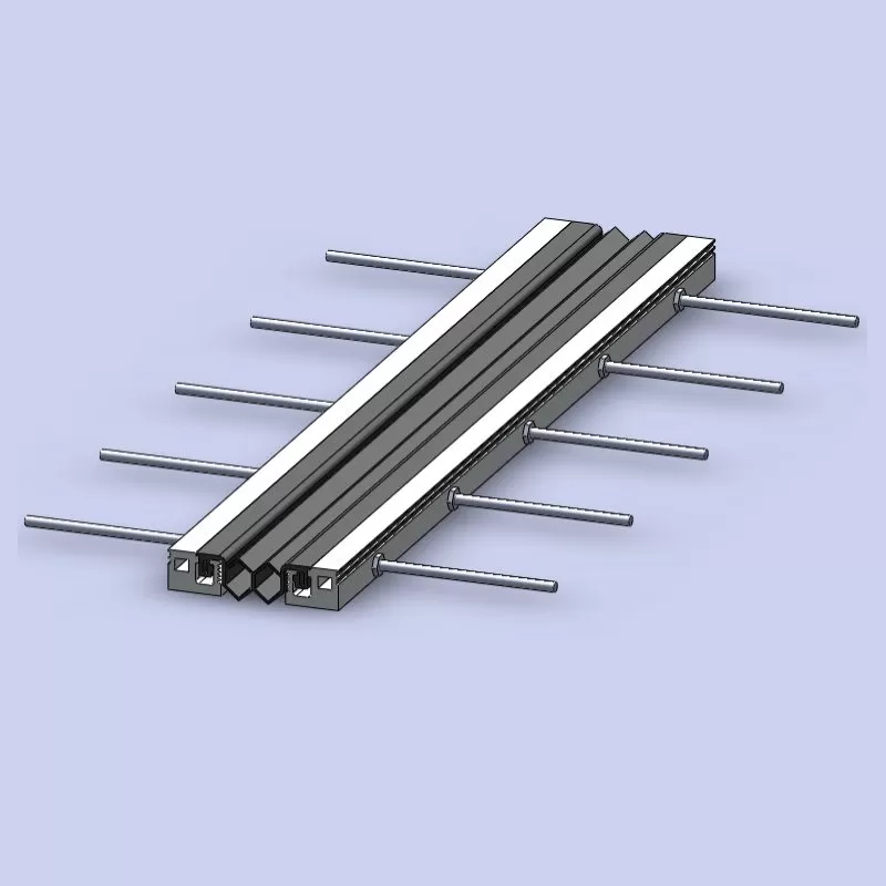
2.4 Modular Expansion Joints
For large movements exceeding 100 mm (typical in long-span bridges or skewed structures), modular joints employ multiple strip seal glands supported by a central beam system. The number of glands ranges from two to over ten. These systems incorporate sophisticated control springs and sliding supports to distribute movement evenly. However, they are heavy, costly, and require periodic alignment inspections. KINGWORK has supplied prefabricated modular joint assemblies for coastal bridges where high chloride exposure demands duplex stainless steel edge rails.
2.5 Finger (Tooth) Plate Joints
Steel comb plates welded to one side of the joint and sliding over the opposing plate. Used for movements up to 500 mm, often in seismic areas or long viaducts. The open gap between teeth allows debris and water to pass through, so a waterproof membrane below the joint is mandatory. Finger joints produce moderate noise levels but offer excellent load transfer and low maintenance if the teeth are designed with proper radii to avoid fatigue cracking.
3. Engineering the Interface: Concrete Edge Beam Detailing
The joint system’s performance is inseparable from the concrete edge beam that supports the anchorage. Many premature failures originate not from the joint itself but from concrete spalling behind the rail. Key design and construction rules:
Minimum edge distance: The distance from the joint centerline to any free edge or construction joint should be at least 300 mm for strip seals, and 450 mm for modular systems.
Reinforcement congestion: U-bars and horizontal stirrups must be provided within 150 mm of the joint face to confine concrete and resist bursting forces from anchor bolts under fatigue loading.
High-performance concrete (HPC): The joint backfill zone (usually 300–500 mm wide) should use low-shrinkage, high-early-strength concrete with a minimum compressive strength of 50 MPa and chloride diffusion coefficient below 2.0 × 10⁻¹² m²/s.
Debonding of top reinforcement: Steel reinforcing bars crossing the joint plane must be debonded (greased sleeve) for at least the movement range to prevent unintended restraint.
Field inspections frequently reveal that anchor bolt pull-out occurs because concrete edge beams were cast with inadequate vibration or poor curing. Therefore, project specifications must mandate non-destructive testing (NDT) of concrete cover and embedment depth after installation. KINGWORK’s technical team provides on-site concrete quality verification for all supplied joint systems, ensuring anchorage capacity meets AASHTO or Eurocode requirements.
4. Load Transfer Mechanisms and Fatigue Life Prediction
Every concrete deck expansion joint transfers wheel loads through either direct bearing (tooth plates, sliding plates) or elastomeric compression (strip seals). For strip seal systems, the steel edge rails take the vertical load via a continuous weld or bolted connection to the anchor frames. Finite element analysis (FEA) of the rail-concrete interface shows that stress concentrations at the anchor bolt holes govern fatigue life. Using the S-N curve for Class C details (AASHTO), the permissible stress range for anchor bars is typically 70–100 MPa for infinite life (over 2 million cycles).
Fatigue failures usually initiate from:
Undersized fillet welds connecting the edge rail to anchor plates – a common fabrication flaw.
Lack of backer bars allowing weld root cracking.
Galvanic corrosion at dissimilar metal contacts (e.g., carbon steel bolts in stainless steel rails).
To achieve a 75-year design life in high-traffic corridors, specify:
Anchor bars with full penetration groove welds and post-weld heat treatment (when using quenched and tempered steel).
Cathodic protection or epoxy-coated reinforcement in the joint zone for marine or deicing salt environments.
Regular torque checks of bolted rail splices – every 5 years for moderate traffic, every 2 years for extreme heavy-haul routes.
Laboratory testing by independent institutes demonstrates that properly designed strip seal joints withstand 5 million cycles of 100 kN wheel load without significant degradation, provided the edge concrete remains intact. This aligns with the design requirements for European motorway bridges (Load Model 1 per EN 1991-2).

5. Waterproofing and Drainage Integration
A common misunderstanding is that the expansion joint itself provides total waterproofing. In reality, all mechanical joints allow some moisture ingress over time. The industry best practice integrates the joint with a deck waterproofing membrane that extends at least 300 mm past the edge rail and terminates into a sealed drip edge. For reinforced concrete box girders, internal gutters should be installed directly below the joint to capture any leakage and drain it away from bearing seats and girder ends.
KINGWORK offers pre-assembled joint systems with factory-applied hydrophilic waterstops that swell upon contact with water, creating a secondary seal. Additionally, for joints on steep grades (over 4%), consider specifying a center drainage channel within the joint to prevent ponding that accelerates seal degradation.
6. Installation Workflow and Quality Control (QC) Checklist
Field installation remains the highest risk factor for premature failure. A systematic QC workflow includes:
Concrete edge preparation: Abrasive waterjet cutting of the joint slot to achieve a ±5 mm tolerance on width and depth. Avoid impact breakers that microfracture concrete.
Anchor frame setting: Suspend the frame using leveling bolts; verify alignment using a 3-meter straightedge – maximum gap of 1.5 mm beneath the straightedge.
Concrete backfill: Use polymer-modified shrinkage-compensated concrete or ultra-high-performance concrete (UHPC) with a maximum aggregate size of 10 mm. Place and consolidate with high-frequency needle vibrators. Curing period of at least 72 hours with wet burlap or curing compound.
Elastomeric seal installation: Lubricate the gland insertion zone with manufacturer-recommended lubricant (never petroleum-based, which attacks EPDM). Stretch the seal uniformly – overstretching reduces compression set resistance.
Protection against early trafficking: No heavy vehicle traffic for 7 days; light traffic allowed after 3 days only if concrete strength reaches 80% of design.
Failure to follow any of these steps has been the direct cause of joint failures within 18 months on numerous projects. Independent third-party inspection during concrete placement is strongly recommended for critical infrastructure.
7. Common Distress Modes and Remedial Strategies
During routine bridge inspections (annually or biennially), engineers encounter several distress patterns:
Spalled concrete at the joint face: Typically caused by insufficient edge distance or poor consolidation. Repair by saw-cutting 150 mm back, installing new deformed bars mechanically anchored into the parent concrete, and casting a high-strength repair mortar with bonding agent.
Extruded or torn seal: Indicates either excessive movement (joint was undersized) or debris trapped in the gap. Replace the seal and implement a quarterly joint cleaning program – mechanical sweepers with high-pressure air.
Rust staining emanating from anchor bolts: Suggests crevice corrosion. Drill test holes to assess bolt condition. If cross-section loss exceeds 15%, replace bolts with duplex stainless steel (e.g., 2205 grade) and inject corrosion inhibitor around the embedment zone.
Step height difference between deck and joint rail: Caused by settlement of the backfill concrete or worn rail top. Grind the higher side and apply a polymer wearing course; if differential exceeds 6 mm, full-depth replacement of the joint assembly is required.
Proactive owners implement a lifecycle management strategy: inspect every 2 years, pressure-clean and reseal the joint-concrete interface every 5 years, and replace elastomeric glands every 12–15 years. This reduces total ownership cost by 40% compared to reactive repairs after complete failure.
8. Material Selection for Extreme Durability
For bridges in coastal zones, industrial areas, or cold regions with heavy salting, standard carbon steel components will not achieve the target service life. Advanced material options include:
Stainless steel edge rails (UNS S32304 or S32205): Approximately 3–4 times the initial cost of galvanized steel, but eliminates corrosion maintenance for 50+ years. Lifecycle cost analysis favors stainless for locations within 1 km of seawater.
Aluminum extrusions for modular joints: Lightweight and corrosion resistant, but susceptible to galvanic attack when in contact with carbon steel reinforcement. Use isolation pads.
Polyurethane or silicone sealants for compression seals: Silicone offers superior UV and ozone resistance but lower tear strength than polyurethane. Hybrid systems combining silicone with polyurethane coating provide balanced properties.
KINGWORK manufactures a full range of joint systems with material certifications traceable to mill sources. For marine bridge projects, KINGWORK supplies hot-dip galvanized plus acrylic topcoat as a standard corrosion protection system that exceeds ISO 12944 C5-M requirements.
9. Specification Writing Guide for Bridge Engineers
When preparing contract documents for a concrete deck expansion joint replacement or new construction, include the following performance criteria:
Movement capability: Minimum service movement range of +100% to -50% of design movement (e.g., for ±40 mm design, the joint must survive ±60 mm without damage).
Fatigue testing: Provide test reports from an accredited lab showing 2 million cycles at load range equal to 1.5 times the factored wheel load without any crack growth or seal pull-out.
Watertightness: Under a 5 kPa water pressure for 1 hour, leakage shall not exceed 10 ml per meter of joint length.
Skew accommodation: Joints must function at skew angles up to 45° without decreasing movement capacity.
Installation tolerance: Finished surface flush to deck within 1.5 mm.
Avoid generic phrases like “proven system” without requiring data. Instead, request certified test records from at least three similar projects with comparable traffic and climate.
10. Common Questions from Bridge Owners and Contractors
Q1: What is the typical service life of a concrete deck expansion
joint in a highway bridge?
A1: With proper material selection (strip
seal with galvanized rails and silicone gland) and annual cleaning, you can
expect 20–25 years for moderate traffic (AADTT 5,000). For extreme heavy-haul
corridors, 12–15 years before seal replacement is typical. Edge rail corrosion
rather than gland fatigue usually determines the replacement cycle.
Q2: Can we use the same joint system for both curved decks and skewed
abutments?
A2: Yes, but modifications are required. For curved
decks, the joint gap width changes along the arc. Use a modular joint with
variable gland lengths or specify a custom-fabricated finger joint cut to the
curved geometry. For skews above 20°, standard strip seals tend to rack
(non-uniform compression), so you need a joint with articulated edge rails or a
pre-compressed foam sealant system. KINGWORK provides skew-compensating designs
validated by 3D motion simulation.
Q3: Why does my joint leak even though the gland looks
intact?
A3: Most leakage occurs at the interface between the gland
and the steel edge rail, not through the gland body. Contaminants like fine sand
or chloride residue break the seal’s lip contact. Remove the gland, thoroughly
clean the rails with a wire brush and alcohol, then reinstall with a
factory-supplied lubricant. Also, check the drainage outlets directly beneath
the joint—if they are clogged, water will pond and find any micro-gap.
Q4: How do we handle expansion joints in bridges subject to seismic
movement?
A4: Seismic design requires joints capable of
accommodating both thermal movements (slow, cyclic) and seismic displacements
(large, one-time or few cycles). A typical solution is a “seismic joint” with
reinforced edge beams and a sacrificial shear key. Use finger plates with
sliding bearings that allow ±200 mm longitudinal and ±50 mm transverse
displacements. After a major event, the joint must be inspected for plastic
deformation of the finger plates. KINGWORK’s seismic modular joints incorporate
energy-dissipating dampers for high-risk zones.
Q5: Can we retrofit an old bridge with a new concrete deck expansion
joint without closing the bridge completely?
A5: Full closure of at
least one lane is necessary for safety and concrete curing. However, you can
replace joints in phases using modular temporary steel plates (ramped) covering
the open gap for night traffic. Night work with fast-setting UHPC (4-hour
strength >30 MPa) allows lane reopening by morning. Many agencies perform
this during weekend closures. Always have a detailed traffic management plan and
consider prefabricated joint assemblies to minimize on-site work time.
Conclusion and Inquiry Guidance
Selecting and maintaining a concrete deck expansion joint demands a system-level approach that integrates structural analysis, material durability, installation precision, and lifecycle inspection. Substandard joints lead to cascading failures—leaking water damages bearings and pier caps, step differences accelerate dynamic loading, and corroded anchors compromise load transfer. By adhering to the engineering principles outlined above—movement verification, fatigue-rated details, high-performance concrete edge beams, and proactive maintenance—bridge owners can achieve 50+ years of reliable service from their deck expansion systems.
KINGWORK brings over two decades of specialized manufacturing and technical support for concrete deck expansion joints, modular systems, and seismic articulations. Our engineers assist from specification development through installation supervision and post-commissioning inspection. For project-specific load requirements, movement calculations, or material upgrade recommendations, contact our infrastructure team directly.
Request a technical
consultation or detailed quotation:
Send your bridge parameters
(span length, movement range, AADTT, climate zone, and current joint details) to
our engineering department. We respond within 48 hours with preliminary sizing,
fatigue life estimate, and budget cost.