Bridge Expansion Joint Detail: Engineering Specifications & Design Guide
Article content and related resources
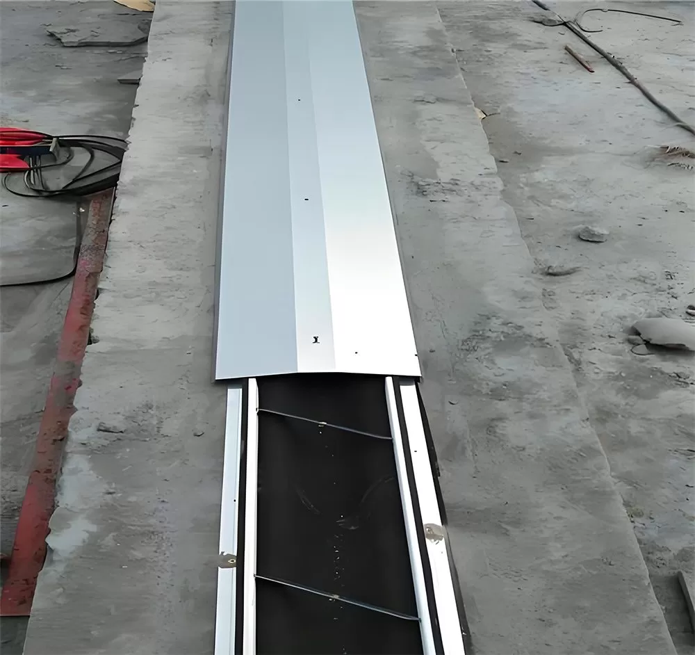
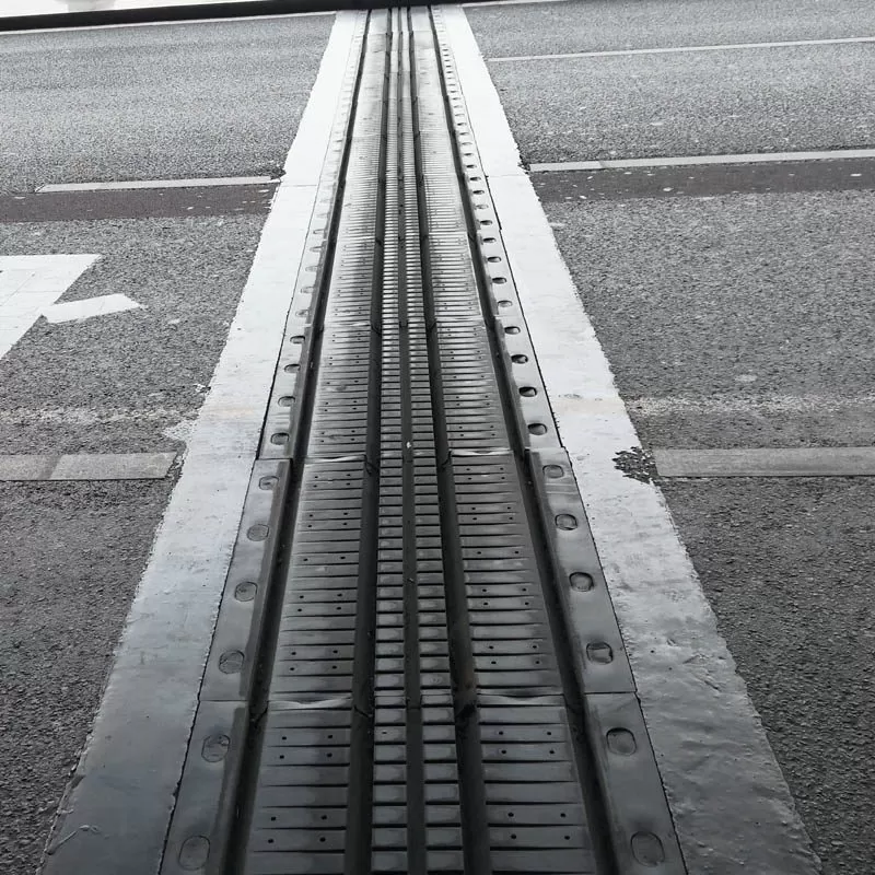
Bridge superstructures undergo continuous volumetric and geometric changes throughout their operational lifespan. Thermal variations, concrete shrinkage, long-term creep, live load deflections, braking forces, and seismic accelerations induce continuous displacements across deck boundaries. Without adequate structural discontinuities, these induced deformations generate severe internal stresses that can compromise abutments, piers, and deck slabs. A properly engineered bridge expansion joint detail functions as the primary mechanical interface designed to accommodate these dynamic multidirectional movements while maintaining structural continuity, ride quality, and continuous waterproofing across bridge decks.
Achieving long-term durability at deck joints requires a comprehensive understanding of structural mechanics, material behavior, and installation sequencing. Joint assemblies endure millions of high-impact wheel load cycles, exposure to aggressive chemical deicing agents, and direct exposure to environmental weathering. When engineers formulate a bridge expansion joint detail, structural movement demands must be systematically quantified to select the appropriate mechanical typology, design robust anchorage assemblies, and integrate durable transition headers.
Kinematic Demands and Movement Calculations
The design displacement range of an expansion system governs the selection and detailing of the entire joint mechanism. Movement calculations must account for both longitudinal translation and multi-axis rotations resulting from vehicular loading and superstructure kinematics.
The primary longitudinal thermal displacement ($\Delta L$) is derived through the standard thermal expansion formulation:
$$\Delta L = \alpha \cdot L_{eff} \cdot \Delta T$$
Where:
$\alpha$: Coefficient of thermal expansion of the superstructure material (typically $1.2 \times 10^{-5} /\text{°C}$ for structural steel and $1.0 \times 10^{-5} /\text{°C}$ for normal-weight concrete).
$L_{eff}$: Effective expansion length measured from the fixed structural bearing or the point of zero movement to the joint location.
$\Delta T$: Design temperature differential between the maximum and minimum anticipated bridge temperatures, established by regional design codes such as AASHTO LRFD Bridge Design Specifications or Eurocode 1 (EN 1991-1-5).
Beyond baseline thermal expansion and contraction, bridge kinematics introduce irreversible time-dependent movements and transient rotations. In prestressed and post-tensioned concrete structures, concrete shrinkage strains and compressive creep deformations accumulate over decades, shortening the superstructure and widening joint gaps permanently. Skewed bridges introduce transverse shear displacements and torsional rotations across the joint line, requiring the joint mechanism to tolerate diagonal skew movement vectors without binding or tearing seals.
Anatomical Components of an Expansion Assembly
Every durable bridge expansion joint detail relies on a multi-component assembly designed to absorb dynamic wheel loads, anchor securely into bridge deck reinforcement, and maintain a watertight envelope beneath the roadway surface.
Structural Steel Edge Beams and Profiles
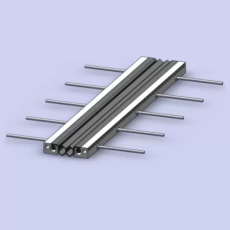
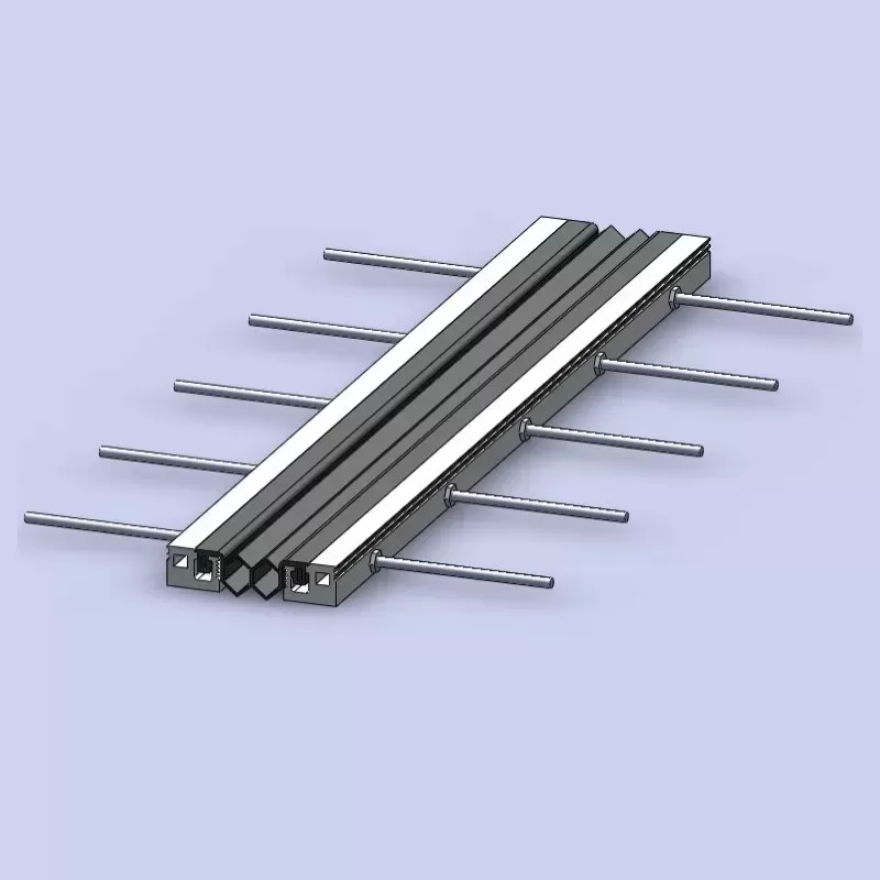
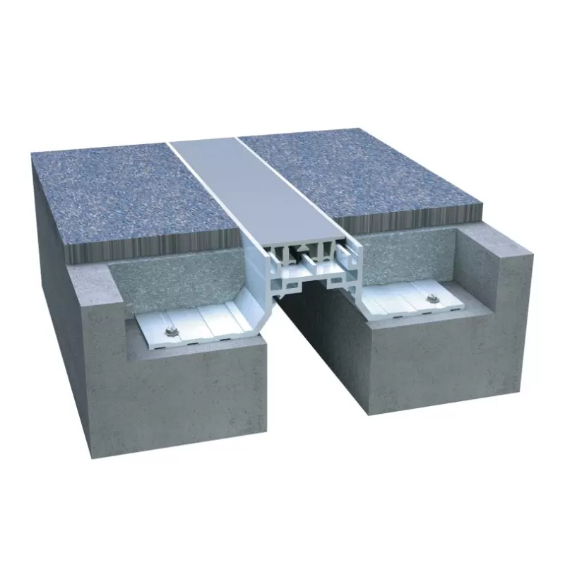
Heavy-duty rolled or extruded steel edge beams define the joint gap and receive direct vehicular wheel impacts. Common steel grades include AASHTO M270 Grade 50 (ASTM A709 Grade 50) or structural atmospheric corrosion-resistant Grade 50W. In assemblies manufactured by specialized structural fabricators such as KINGWORK, heavy-duty extruded edge beams incorporate machined or precision-rolled internal retaining grooves designed to mechanically lock elastomeric sealing elements in place, preventing seal pull-out under extreme dynamic deflections.
Elastomeric Sealing Glands
Watertightness is achieved through preformed elastomeric glands manufactured from virgin polychloroprene (neoprene) or ethylene propylene diene monomer (EPDM). These seals must exhibit high tensile strength (minimum 14 MPa), elongation at break exceeding 350%, and exceptional resistance to ozone deterioration, UV exposure, and petroleum contamination. The profile geometry allows the gland to fold downward or compress uniformly during joint closure without protruding above the deck surface where snowplow blades or heavy vehicle tires could damage the elastomer.
Anchorage and Reinforcement Systems
Dynamic wheel forces transferred to the steel edge beams must be dissipated directly into the primary bridge deck slab. Anchorage designs utilize a combination of structural anchor studs and loop reinforcement:
Headed Concrete Anchors (Nelson Studs): Welded directly to the back of the steel edge profiles at specified center-to-center spacings, providing shear transfer into the surrounding concrete matrix.
Anchorage Rebar Loops: Formed structural reinforcing bars (typically Grade 60 / B500B) welded to the edge beam or base plates, creating a cage that interlocks directly with the longitudinal and transverse deck reinforcement.
Anchor Plates and Stiffeners: Gusset plates positioned at frequent intervals along the extrusion length to prevent lateral deformation of the steel profile under horizontal braking forces.
System Typologies and Movement Range Classification
Selecting the appropriate bridge expansion joint detail requires mapping the structural kinematics to specific mechanical systems categorized by total movement capability.
Single-Gap Strip Seal Systems (Movement: Up to 100 mm)
Strip seal systems represent the standard solution for short to medium-span bridges. The assembly consists of two continuous steel edge beams anchored into the bridge blockouts with a single continuous elastomeric gland spanning the expansion gap. Strip seals provide complete continuity across the bridge cross-section and can be fabricated with factory-welded upturns at curbs, barriers, and parapets to ensure complete watertight containment.
Modular Bridge Joint Systems (Movement: 100 mm to Over 1000 mm)
For long-span cable-stayed, suspension, and continuous multi-span structures, single-gap systems cannot accommodate the vast movement ranges. Modular bridge joint systems (MBJS) divide the total movement range into multiple smaller gaps separated by steel center beams. Support bars oriented longitudinally beneath the center beams maintain uniform spacing via mechanical control springs or urethane control cushions. Advanced fabricated movement systems, including those engineered by KINGWORK, incorporate multi-layer elastomeric sliding bearings and pre-compressed control mechanisms to maintain equal gap distribution across extreme dynamic displacement events.
Finger and Sliding Plate Expansion Joints
Cantilevered or supported steel finger joints are deployed where large longitudinal displacements occur with minimal vertical movement. Interlocking steel tooth plates span the gap, providing a continuous riding surface that reduces impact noise and vehicular vibration. Because finger joints are inherently open mechanisms, continuous sub-deck drainage troughs fabricated from reinforced elastomers or stainless steel must be suspended beneath the finger plates to channel runoff water and deicing chlorides away from the substructure.
Buried and Flexible Plug Systems (Movement: Under 40 mm)
For small-movement bridges, asphaltic plug joints (APJ) create a seamless, continuous pavement surface. The joint uses a specialized polymer-modified asphalt binder mixed with selected single-size granite aggregates installed over a steel bridging plate. While providing a quiet ride, asphaltic plugs exhibit limited tolerance for rapid structural rotations and heavy shear braking stresses compared to mechanical steel-reinforced systems.
Blockout Geometry, Sub-Surface Drainage, and Concrete Transitions
The interface between the deck slab and the joint assembly forms the anchor zone of the bridge expansion joint detail. Structural durability depends on the geometry of the recess, the properties of the infill material, and proper water management interfaces.
Blockout Geometry and Preparation
The blockout is a pre-formed recess in the bridge deck slab designed to receive the steel edge profiles and anchor reinforcement. Typical blockout dimensions require a depth of 200 mm to 350 mm and a width ranging from 300 mm to 600 mm on each side of the expansion gap, depending on movement capacity. Prior to installing the expansion frame, concrete contact surfaces must be prepared to an International Concrete Repair Institute (ICRI) concrete surface profile (CSP 5 to CSP 7) via hydro-demolition or mechanical scarification to ensure structural bonding.
Transition Headers and Bedding Materials
Standard structural deck concrete often exhibits shrinkage cracking around dense anchor cages. Modern specifications frequently demand specialized header materials to surround the joint anchors:
Elastomeric Concrete: A three-component polyurethane or epoxy-based matrix mixed with selected aggregates. It possesses high compressive strength combined with a low modulus of elasticity, absorbing dynamic shock loads and preventing edge spalling adjacent to the steel beams.
High-Performance Non-Shrink Concrete: Micro-silica modified, fiber-reinforced fast-setting concrete mixtures that achieve compressive strengths exceeding 35 MPa within 24 hours, minimizing lane closure durations during maintenance works.
Waterproofing Membrane Termination
Runoff water containing dissolved salts represents the primary cause of substructure deterioration. The deck waterproofing sheet membrane must extend fully into the blockout area and terminate against the outer face of the steel edge beam. A continuous elastomeric mastic or clamping seal prevents moisture from tracking beneath the waterproof membrane and reaching the reinforcement steel.
Installation Tolerances and Temperature Preset Calculations
During bridge construction, placing the bridge expansion joint detail according to ambient thermal offsets prevents premature mechanical binding or over-extension.
Fabrication plants assemble joint units with temporary shipping fixtures or turnbuckles holding the edge beams at a specific gap opening calibrated to a standardized reference temperature (commonly 15°C / 60°F). Before cast-in-place concrete or elastomeric headers are poured, field engineers must measure the actual bridge deck temperature and adjust the gap width according to the setting formula:
$$W_{install} = W_{ref} - \alpha \cdot L_{eff} \cdot (T_{deck} - T_{ref})$$
Where $W_{ref}$ is the nominal gap at $T_{ref}$, and $T_{deck}$ is the bridge core temperature measured via embedded thermal probes. Strict tolerance criteria must be maintained during installation:
Surface Flushness: The top surface of the joint profile must be installed 2 mm to 4 mm below the adjacent finished wearing course level to prevent snowplow impacts and direct wheel hammering.
Cross-Slope Alignment: Joint profiles must match the transverse roadway cross-slope precisely across traffic lanes and shoulders.
Anchor Interlocking: Anchor loops must be securely tied or welded to the bridge deck main rebar mat; tack welding must follow AWS D1.4 Structural Welding Code for reinforcing steel.
Fatigue Resistance and Long-Term Durability
Expansion joints operate under severe dynamic fatigue environments. Unlike main structural bridge girders, which experience globally distributed loads, joint edge rails receive direct, concentrated, unattenuated axle impacts from heavy freight transport.
Structural fatigue evaluations follow AASHTO LRFD specifications under Fatigue I and Fatigue II limit states. Key considerations include:
Dynamic Load Allowance (Impact Factor): Joint design must apply an impact factor up to 75% above standard static axle loads to represent dynamic wheel impacts over the surface gap.
Welded Connection Categories: Welds connecting anchor studs, support boxes, and center beams are categorized under fatigue detail classes (Category C, D, or E). Welded details must avoid high stress concentrations to prevent fatigue cracking under cyclic loading.
Debris Accumulation Resistance: Joint gaps must resist the intrusion of incompressible road debris, gravel, and sand. Trapped debris prevents natural joint closure during hot summer months, inducing severe lateral forces that can shear blockout anchor bolts.
Frequently Asked Questions
What is the difference between a strip seal joint and a modular expansion joint?
A strip seal joint utilizes a single continuous elastomeric gland locked between two steel edge beams, accommodating total longitudinal movements up to 100 mm (4 inches). A modular bridge joint uses multiple intermediate steel center beams supported by internal sliding bars to subdivide larger movements into multiple independent gaps, accommodating displacements from 100 mm to over 1000 mm.
How is the gap width set for a bridge expansion joint detail during concrete pouring?
The gap width is adjusted on-site immediately prior to anchoring by measuring the representative superstructure temperature. Installation crews adjust mechanical presets based on a pre-calculated temperature-movement chart, ensuring the joint possesses sufficient capacity to close during maximum summer temperatures and expand during extreme winter cold.
Why do concrete headers adjacent to expansion joints frequently fail?
Failures commonly result from differential stiffness between the rigid steel joint profile and the surrounding asphalt pavement, combined with inadequate concrete consolidation beneath dense anchor reinforcement. Applying flexible elastomeric concrete or fiber-reinforced, non-shrink grout headers significantly reduces impact spalling and improves stress distribution.
How often should elastomeric seals be inspected and replaced?
Sealing glands should undergo visual inspection every 12 to 24 months for signs of tearing, debonding from steel retainers, debris accumulation, or puncture damage. Under standard operating conditions, high-quality polychloroprene or EPDM seals have an operational lifespan of 15 to 20 years, whereas the surrounding steel structural frame is designed to match the 50 to 75-year bridge design life.
What methods prevent water leakage around expansion joint curb upstands?
Joint edge profiles and elastomeric seals are factory-fabricated with continuous, non-welded vertical or angled upturns that follow the barrier and curb geometry. The continuous vulcanized seal extends vertically above the maximum roadway runoff level, preventing water and corrosive deicing salts from bypassing the drainage plane and contacting the bridge bearing seats below.
For structural project inquiries, engineering data sheets, or layout specifications regarding KINGWORK movement control solutions, contact the engineering support department at info@kwbridgebearing.com / sales@kwbridgebearing.com.