
7 Engineering Principles Governing Spherical Bridge Bearing Performance
Article content and related resources
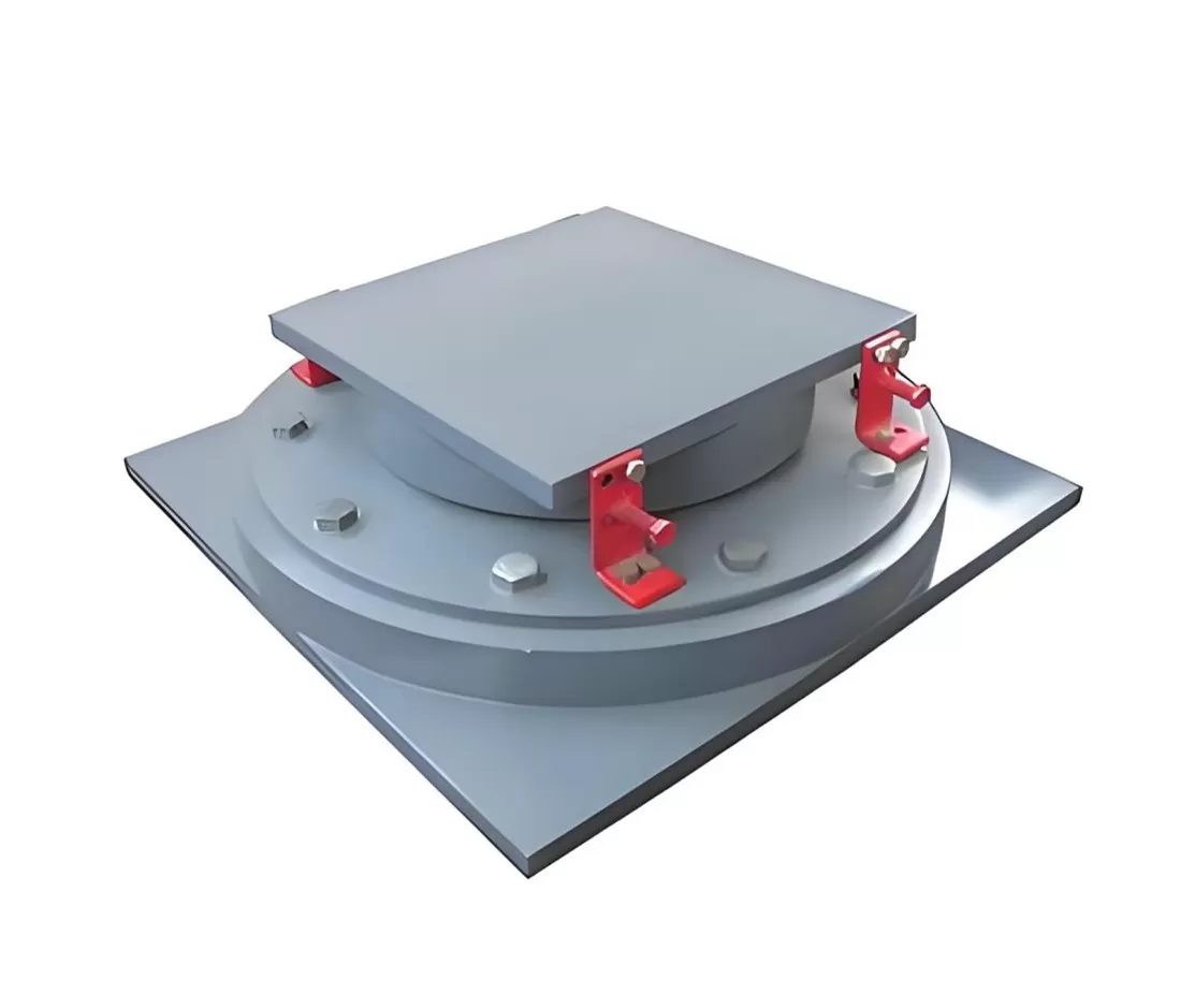
Bridge structural design requires mechanisms capable of transmitting vertical and horizontal forces between the superstructure and substructure while accommodating thermal movement, structural deflection, and concrete creep. As structural spans increase and geometry becomes more complex, traditional elastomeric or pot bearings often reach their operational limits. A modern spherical bridge bearing isolates these kinematic forces through pure rotational sliding across curved surfaces, offering low-friction multi-directional movement without generating concentrated edge pressures on supporting piers.
Engineers specify these mechanical assemblies for civil infrastructure projects that demand high vertical load capacities alongside multi-axis rotational freedom. Understanding the mechanical interaction, material selection, and structural performance criteria is vital for achieving designed service life operational parameters across highway viaducts, railway bridges, and complex cable-stayed structures.
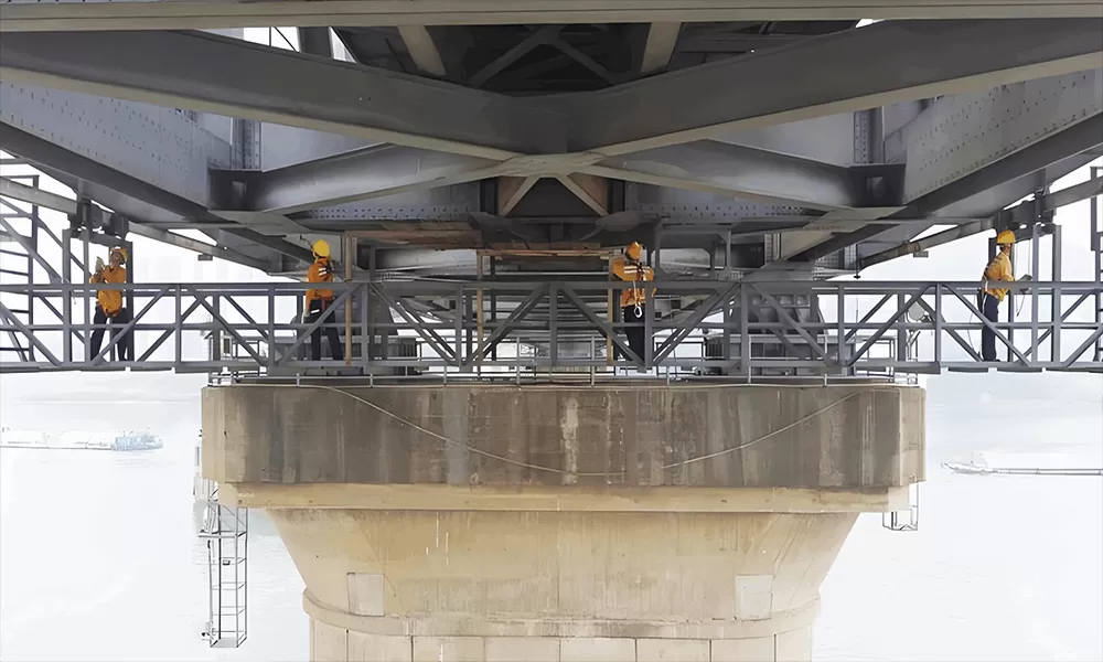
Mechanical Kinematics and Structural Load Transfer
The primary function of a bridge bearing assembly is to facilitate structural movement without imposing damaging secondary moments onto substructure components. The mechanical behavior of a spherical bridge bearing relies on two distinct functional interfaces: a primary spherical sliding surface that handles angular rotation and an optional flat upper sliding surface that permits horizontal translation.
The rotational mechanism consists of a convex steel pad mating precisely with a concave steel base plate. The interface between these components is lined with a self-lubricating fluoropolymer material—typically dimpled polytetrafluoroethylene (PTFE) or ultra-high-molecular-weight polyethylene (UHMWPE)—paired with a mirror-polished stainless steel sheet. When the bridge deck undergoes flexural rotation due to traffic loading or live load deflection, the convex pad rotates smoothly within the concave recess. This geometry maintains an even distribution of compressive stress across the contact surface regardless of the rotation angle.
Translational movement (longitudinal and transverse movement caused by thermal expansion, contraction, and concrete shrinkage) occurs at the upper horizontal interface. Structural configurations fall into three distinct functional categories:
Fixed Bearings: Contain no horizontal sliding surfaces. Rotation is permitted in all axes, but lateral movement is fully constrained by external shear keys or internal mechanical stops.
Guided Sliding Bearings: Feature a flat sliding plane with directional guide bars. Thermal expansion and contraction are permitted along a single axis (typically longitudinal), while lateral displacement is restricted.
Free Sliding Bearings: Incorporate unconstrained horizontal sliding interfaces, allowing multi-directional longitudinal and transverse deck movement alongside full rotational capacity.
Material Specifications and Manufacturing Tolerances
Structural reliability over decades of operation depends on strict adherence to material standards and machining precision. Structural steel components, typically conforming to EN 10025 (e.g., S355J2+N or S460N) or ASTM A709 standards, form the structural shell of the assembly. Manufacturers like KINGWORK execute precision machining on CNC spherical vertical lathes to achieve exact concave radii, ensuring complete surface contact across the primary load path.
The sliding interface materials require precise tribological properties to maintain low friction under heavy compressive stresses. Key material components include:
Austenitic Stainless Steel Sheets: Manufactured from AISI 316L (1.4404) steel, ground and polished to a surface roughness ($R_a$) below 0.1 µm. This micro-smooth finish minimizes abrasive wear on the mating fluoropolymer liner.
Fluoropolymer Sliding Liners: High-density PTFE or modified UHMWPE sheets fitted into machined recesses within the steel backing plates. The surface features dimples filled with specialized silicone grease to maintain lubrication during long periods of micro-sliding.
Corrosion Protection Systems: Exposed steel surfaces undergo multi-layer protective treatments, such as thermal zinc spray coating followed by epoxy-polyurethane paint systems, satisfying ISO 12944 requirements for C4 or C5 atmospheric corrosivity categories.
Standard design limits for the dynamic coefficient of friction at these interfaces generally range from 0.01 to 0.03 under maximum design loads. Lower friction values significantly reduce thermal force transfer to concrete pier caps and abutments, allowing for leaner substructure design.
Comparative Evaluation: Spherical Bearings vs. Pot and Elastomeric Systems
Choosing the correct structural support assembly requires evaluating performance limits under varying structural conditions. While elastomeric pads and pot bearings offer cost-effective solutions for short-to-medium spans, a spherical bridge bearing relies on sliding contact rather than elastomeric deformation, making it superior in demanding applications.
Elastomeric bearings accommodate rotation through non-uniform shear deformation of internal rubber layers. Under high rotation angles ($> 0.01\text{ rad}$), this non-uniform compression induces high localized stresses along the edges of the bearing pad, accelerating rubber fatigue and causing eccentric loading on the supporting concrete. Similarly, pot bearings utilize an internal elastomeric disk confined within a steel cylinder to act as a fluid mass. High dynamic rotations can cause the elastomer to extrude past the brass sealing rings, leading to premature mechanical breakdown.
By contrast, spherical assemblies separate structural rotation from horizontal displacement entirely. Rotational capacities easily exceed $0.05\text{ rad}$ without modifying the stress distribution across the sub-plate. Consequently, specifying a high-capacity spherical bridge bearing prevents excessive localized compression and structural fatigue under heavy dynamic traffic loads.
Structural Application Scenarios and Engineering Integrations
Complex bridge geometries require advanced support solutions. High-capacity spherical assemblies are implemented across several challenging bridge design scenarios:
Long-Span Cable-Stayed and Suspension Bridges: High vertical forces paired with significant wind-induced dynamic rotations require bearings capable of supporting downward loads exceeding 100 MN while accommodating constant angular oscillations.
Curved Viaducts and Skew Bridges: Non-linear bridge geometries generate complex multi-directional displacement vectors and twisting moments. Guided and free-sliding spherical configurations accommodate these non-parallel movement paths cleanly.
High-Speed Rail Bridges: Track structure stability demands rigid vertical stiffness to prevent rail deflection. Unlike elastomeric bearings that compress under live loads, steel-to-steel spherical structures provide high vertical stiffness with minimal instantaneous deflection.
Seismic Resistance Zones: Custom bearing solutions engineered by KINGWORK integrate customized seismic restraint pins or shear keys designed to yield or shear at controlled lateral force thresholds during seismic events, protecting adjacent substructures.

Installation Methodologies and Quality Inspection Protocols
Proper field installation ensures that designed kinematic behavior translates to actual bridge performance. Improper leveling or incorrect preset adjustments during installation are primary causes of premature wear on sliding liners.
During construction, the lower bearing plate is set onto a high-strength, non-shrink epoxy grout bed placed over the pier cap. Precision leveling screws adjust the assembly to within strict planar tolerances (typically less than $1\text{ mm/m}$). Alignment pins or shipping brackets lock the top and bottom plates together during transport and positioning to preserve internal component factory alignment.
If installation occurs at temperatures differing from the median design temperature, field engineers must offset the top sliding plate relative to the base plate. This pre-setting calculation accounts for future thermal contraction or expansion of the bridge deck, ensuring the top plate remains within its allowable sliding range throughout seasonal temperature cycles.
Routine maintenance programs involve periodic visual and dimensional inspections. Field inspection teams measure structural clearance gaps between steel plates, verify the integrity of elastomeric dust seals protecting internal sliding surfaces, check for signs of anchor bolt corrosion, and measure sliding offsets to verify that deck movement aligns with thermal calculation models.
Frequently Asked Questions
Q1: What is the primary functional difference between a spherical
bearing and a pot bearing?
A1: A pot bearing relies on the hydraulic
deformation of a confined elastomeric pad to accommodate rotation, which can
wear out under high dynamic rotation angles. A spherical bearing uses mechanical
sliding between a polished stainless steel sphere and a fluoropolymer liner,
enabling much larger rotational capacities without risking seal extrusion or
localized edge pressure.
Q2: How are thermal movements pre-set into the bearing prior to
installation?
A2: Pre-setting involves offsetting the upper sliding
plate relative to the lower assembly based on ambient concrete temperature at
the time of installation. This offset ensures that as the bridge deck contracts
in cold weather or expands in hot weather, the top plate moves within designed
structural boundaries without hitting mechanical limits.
Q3: What design standards govern the load capacity and fabrication of
these assemblies?
A3: Global structural projects typically follow
standard codes such as EN 1337-7 (Structural Bearings - Spherical and
Cylindrical PTFE Bearings), AASHTO LRFD Bridge Design Specifications, or
regional equivalents. These standards govern allowable surface stresses,
friction factors, material chemistry, and non-destructive testing
requirements.
Q4: Why is stainless steel used on the sliding surface rather than
carbon steel?
A4: Stainless steel (such as AISI 316L) resists
atmospheric corrosion and pitting. A smooth, corrosion-free surface is necessary
because surface roughness or rust spots on carbon steel would rapidly tear the
softer fluoropolymer (PTFE/UHMWPE) sliding sheet, resulting in high friction and
mechanical binding.
Q5: What maintenance procedures are required over a 50-year service
life?
A5: Spherical units are designed to be largely
low-maintenance. Practical oversight requires semi-annual visual inspections of
dust seals, monitoring movement indicators, checking anchor bolt torque, and
measuring the remaining thickness of the sliding liner to ensure the sub-plates
do not make metal-to-metal contact.
Engineering Collaboration and Project Inquiries
Proper selection, sizing, and structural integration of structural support components demand rigorous engineering analysis tailored to exact site conditions, load combinations, and movement envelopes. Selecting the appropriate spherical bridge bearing for specific load requirements ensures long-term operational integrity and reduced maintenance expenditure over the structural lifespan of civil infrastructure projects.
Engineering teams and procurement managers preparing technical specifications for highway, rail, or bridge construction projects can consult with KINGWORK structural specialists to receive tailored engineering calculations, structural drawings, and project-specific quotations for custom bridge bearing assemblies.
![Bridge Joint Types: The Complete Engineering Guide [2026 Edition]](https://www.kwbridgebearing.com/storage/non_theme/202606/024.webp)