5 Structural Principles for the Seismic Design of Buckling Restrained Braced Frames
In high-seismic regions, structural engineering practices require lateral force-resisting systems (LFRS) that combine high stiffness with superior energy dissipation capacity. Traditional lateral systems, such as Concentrically Braced Frames (CBFs), possess structural limitations under severe cyclic loading. When subjected to compression forces during an earthquake, standard structural braces undergo global buckling. This leads to a severe reduction in compressive strength, asymmetric hysteretic behavior, and localized damage at the brace-to-frame connections.
To overcome these limitations, structural engineers rely on advanced energy dissipation systems. Within contemporary structural engineering, the seismic design of buckling restrained braced frames represents a highly reliable methodology for protecting mid-rise and high-rise commercial structures. By preventing global buckling of the structural brace under compression, these systems exhibit stable and symmetric hysteretic loops in both tension and compression, mitigating damage to the surrounding gravity-load-carrying frame.
Anatomy of a Buckling Restrained Brace (BRB)
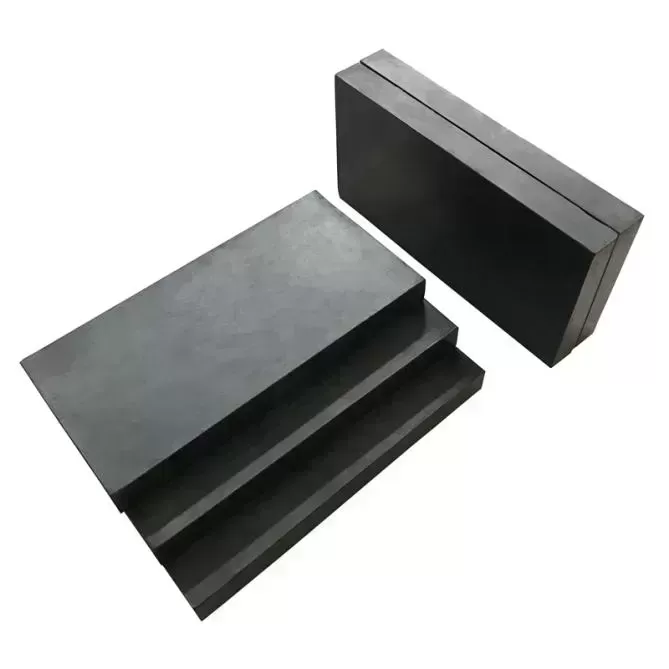
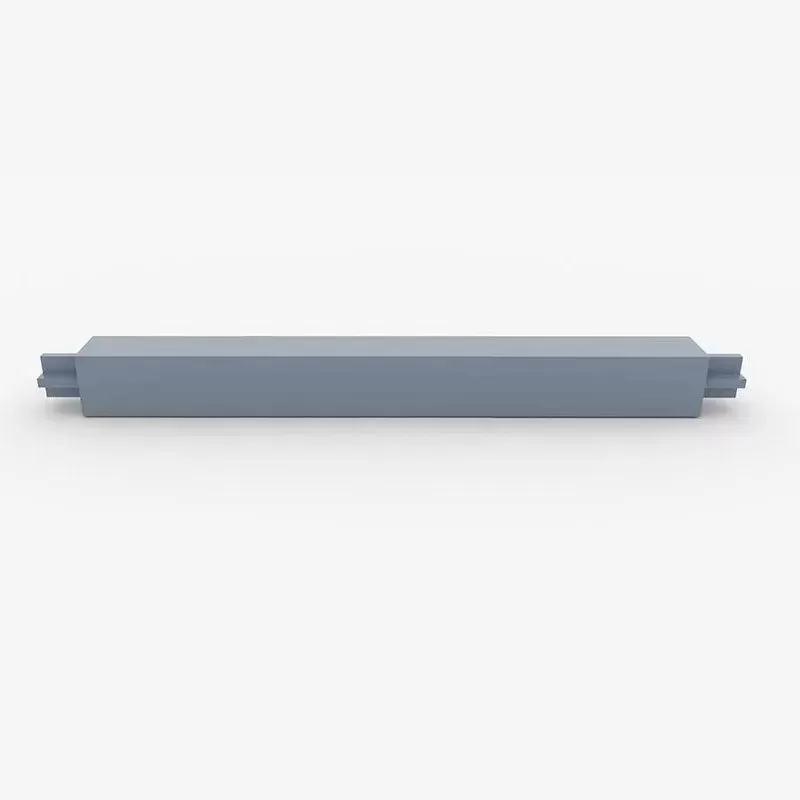
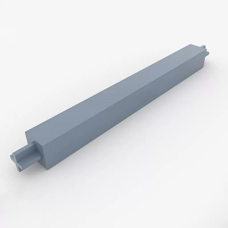
The performance of a buckling restrained braced frame (BRBF) depends on the design and composition of its individual braces. Unlike standard structural steel braces, which rely on the cross-sectional geometry to resist buckling, a Buckling Restrained Brace (BRB) decoupling axial load capacity from lateral stability. The assembly consists of three core components:
The Steel Core Plate: This is the primary load-bearing element, designed to yield under both tension and compression. It is typically made of high-ductility steel, such as Low Yield Strength (LYS) steel or standard structural grades like ASTM A36. The core plate features a slender cross-section along its yield length, which transitions to a wider, reinforced end section to prevent yielding outside the target zone.
The Restraining Casing: To prevent the core plate from buckling laterally when subjected to compressive forces, it is encased in a continuous structural sleeve. This sleeve is typically a hollow structural steel (HSS) section filled with a high-strength self-consolidating cementitious mortar or concrete infill.
The Unbonding Layer: A highly engineered sliding interface is placed between the steel core plate and the mortar infill. This unbonding material (typically a specialized mastic tape, butyl rubber, or a thin polymeric sheet) prevents shear stress transfer from the core to the casing. It provides a physical gap to accommodate the lateral Poisson expansion of the steel core plate as it yields under compression.
For instance, structural engineers collaborate with fabricators such as KINGWORK to specify precise unbonding layer thicknesses. This level of manufacturing control ensures that the restraining casing remains virtually stress-free from direct axial loads, allowing the casing to provide continuous lateral containment without bearing structural forces directly.
Symmetric Hysteretic Performance vs. Conventional Systems
The fundamental distinction between traditional concentrically braced systems and those designed with buckling-restrained properties lies in their energy dissipation efficiency. When a standard diagonal brace buckles, its compression capacity drops to a fraction of its tension capacity. Under repeated seismic cycles, this degradation results in a pinched hysteresis loop, indicating low damping capacity and a high risk of catastrophic connection failure.
In contrast, the steel core of a buckling restrained brace yields stably under tension and compression. Because the casing restrains high-mode buckling, the brace achieves full, plump hysteresis loops. The dissipation of energy occurs through plastic deformation of the core plate, which acts as a structural fuse. This predictable performance reduces the demand on adjacent columns, beams, and foundations, preventing structural collapse during design-basis earthquakes (DBE) and maximum considered earthquakes (MCE).
Mechanics of the Seismic Design of Buckling Restrained Braced Frames
A primary objective during the seismic design of buckling restrained braced frames is to ensure that the braces yield before any other structural components—such as columns, beams, or gusset plate connections—experience inelastic deformation or buckling. This requires a capacity-design approach, where the surrounding frame is designed to resist the maximum forces that the yielding braces can deliver.
1. Capacity-Design Calculations
The design forces for the surrounding frame and gusset connections are derived from the maximum expected strength of the BRBs. This maximum force must account for material overstrength and strain hardening. The design codes define two performance-based correction factors:
Tension Strength Adjustment Factor (ω): This factor accounts for the strain hardening of the core steel plate at design displacement. It is calculated as the ratio of the maximum tension force achieved during testing to the actual yield force of the core plate.
Compression Strength Adjustment Factor (β): This factor accounts for both strain hardening and the additional compression capacity resulting from Poisson expansion and friction against the mortar infill. It is the ratio of maximum compression force to maximum tension force at the design displacement.
The design adjusted brace strengths are formulated as follows:
Adjusted Tension Strength: Pt = ω × Ry × Fy × Asc
Adjusted Compression Strength: Pc = β × ω × Ry × Fy × Asc
Where Ry is the ratio of expected yield stress to specified minimum yield stress, Fy is the nominal yield stress of the steel core, and Asc is the cross-sectional area of the yielding core plate.
2. Modeling and Structural Analysis
Modern structural analysis requires representative modeling of BRB components. In software platforms such as SAP2000, ETABS, or OpenSees, the braces are represented as non-linear truss elements. Structural engineers apply bilinear plastic link elements, incorporating kinematic and isotropic hardening properties, to match the dynamic testing profiles of the manufactured braces. High-rise projects typically utilize non-linear time history analysis (NLTHA) using a suite of ground acceleration records scaled to regional hazard spectra.
Regulatory Codes and Performance Factors
In the United States, design provisions governing the seismic design of buckling restrained braced frames are outlined in AISC 341 (Seismic Provisions for Structural Steel Buildings) and ASCE 7 (Minimum Design Loads and Associated Criteria for Buildings and Other Structures). Comparable standards govern design practices in Europe (Eurocode 8) and Japan.
Under ASCE 7, BRBF systems are assigned highly favorable seismic design parameters due to their exceptional ductility and energy dissipation properties. When designated as the primary lateral force-resisting system, the parameters typically include:
Response Modification Coefficient (R): Typically set at 8, indicating that the design forces for the elastic frame can be reduced significantly, which leads to lighter beam and column sizes.
System Overstrength Factor (Ω0): Set at 2.5, used to design columns and key connections to prevent premature failures prior to brace yielding.
Deflection Amplification Factor (Cd): Typically set at 5.0, used to compute realistic inelastic drift and verify that the building will not damage adjacent properties or suffer excessive non-structural damage.
Structural Engineering Challenges and Design Solutions
While the benefits of specifying BRBF systems are clear, structural engineers must address several design challenges to ensure long-term structural reliability under seismic loads.
Gusset Plate Design and Stability
Because the braces transfer high axial forces to the beam-column joints, the design of the connecting gusset plates is highly complex. The gusset plates must resist both tension and compression forces without buckling. Designers use Thornton’s method to verify the buckling resistance of the gusset plate. Additionally, because the frame undergoes lateral drift, the gusset plates must accommodate rotation. Providing a clear fold-line zone (usually equal to twice the plate thickness) allows the plate to yield in bending under frame drift without causing localized damage to the brace end.
Managing Residual Drift
Because low-yield steel cores have high ductility, they can undergo significant plastic deformation during an earthquake. This can sometimes result in high residual drift—where the building remains tilted after the seismic event. To resolve this concern, engineers often implement a dual system. By combining a buckling restrained braced frame with a space moment-resisting frame, the elastic moment-resisting frame provides a self-centering force that helps restore the structure to its original plumb position.
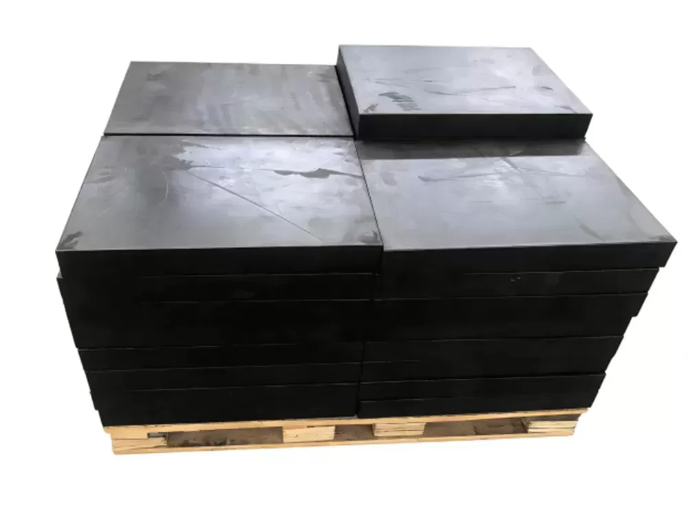
Quality Control, Manufacturing, and Component Validation
The manufacturing precision directly influences the seismic design of buckling restrained braced frames by reducing performance deviation. Unlike conventional structural steel sections, which can be fabricated on-site, a Buckling Restrained Brace must be manufactured under strict factory conditions.
The curing of the mortar infill, the flatness of the core plate, and the application of the unbonding layer require close monitoring. Quality control protocols implemented by suppliers like KINGWORK ensure that the clearance tolerances between the yielding steel core and the internal concrete lining are consistently maintained. Any localized binding between the core and the casing could increase the compression strength adjustment factor (β), transferring unintended forces to the gusset connections and column joints.
To validate the performance of these braces before installation, structural codes require representative prototype testing. AISC 341 outlines rigorous testing sequences, including:
Uniaxial Tension-Compression Testing: Braces must undergo cyclic loading to progressively larger strain levels (reaching multiple times the design story drift) to confirm stable hysteretic behavior without core buckling or casing failure.
Subassemblage Testing: Testing a representative frame portion containing the brace, the gusset plate, and beam-column interfaces to verify that the connections can accommodate the rotation induced by lateral frame deformation.
Frequently Asked Questions
Q1: Can buckling restrained braces be used to retrofit existing structures?
A1: Yes. BRB systems are highly suitable for seismic retrofits of older concrete or steel structures. Because of their high energy dissipation and stiffness, they can reduce building drift and lower the seismic demand on vulnerable columns and foundations, often without requiring extensive foundation strengthening.
Q2: How does a BRB accommodate the lateral expansion of the steel core under compression?
A2: The steel core expands laterally under compressive loads due to the Poisson effect. The unbonding layer, combined with a calculated physical gap between the core plate and the internal mortar, provides the space necessary for this expansion, preventing the transfer of compressive forces to the outer casing.
Q3: What type of steel is typically used for the yielding core of a BRB?
A3: Low Yield Steel (such as LYP160 or LYP225) is frequently preferred because of its low yield point, high elongation capacity, and low cyclic strain hardening. Standard structural steel, such as ASTM A36 or Q355B, is also widely used, provided that the overstrength parameters are verified through material testing.
Q4: Why is a capacity-design approach used for the frame connections in a BRBF?
A4: Capacity design ensures that the non-yielding parts of the structure, such as the beams, columns, and gussets, remain elastic when the BRB yields. This forces all inelastic behavior into the easily replaceable brace core, preventing catastrophic local structural failures.
Q5: What are the primary structural codes regulating the seismic design of buckling restrained braced frames?
A5: The seismic design of buckling restrained braced frames is primarily regulated by AISC 341 (Seismic Provisions for Structural Steel Buildings) and ASCE 7 in the United States, along with corresponding regional codes such as Eurocode 8 or GB 50011 in China.
B2B Procurement and Engineering Consultation
Successful structural design and project execution rely on sourcing highly reliable components from proven manufacturers. For complex infrastructure, high-rise, and institutional projects, the mechanical tolerances of seismic dissipation components must be strictly controlled to verify compliance with all project specifications related to the seismic design of buckling restrained braced frames.
If you are currently evaluating lateral force-resisting systems, preparing a bid for a seismic retrofit, or requiring certified prototype testing documentation for your structural submittals, contact the engineering division at KINGWORK to submit an inquiry and discuss your specific performance requirements with our specialist design staff.