
5 Parameters for Designing Durable Bridge Joints in Modern Highway Projects
Article content and related resources
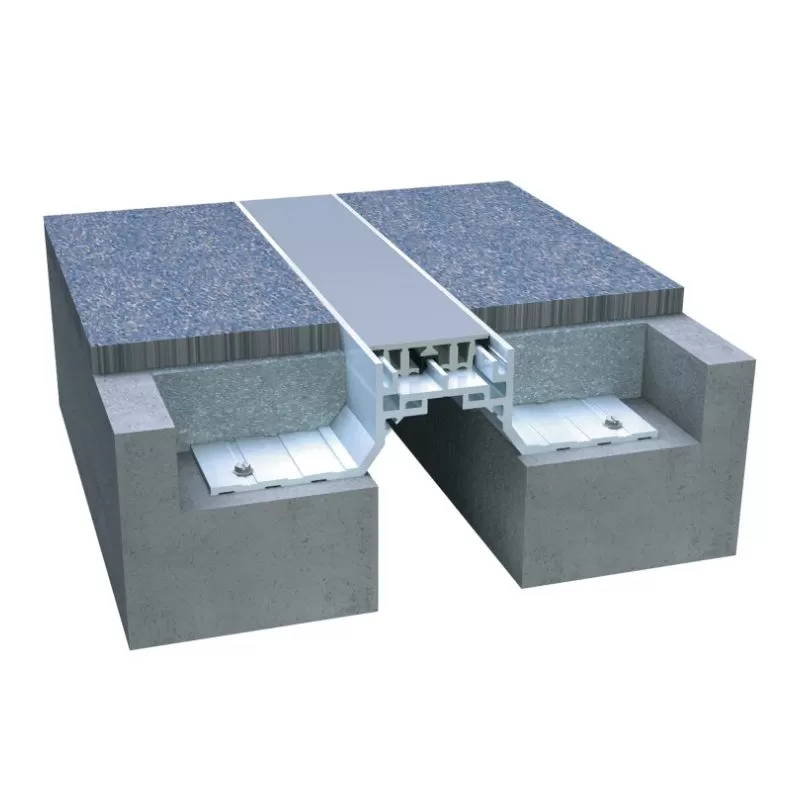
Modern civil infrastructure demands structures that withstand environmental fluctuations, heavy traffic loading, and dynamic forces over many decades. Within bridge engineering, accommodating thermal expansion, concrete shrinkage, and seismic movement is a fundamental design requirement. This structural flexibility is made possible through the implementation of engineered bridge joints. These structural components span the gaps between adjacent bridge spans or between a span and an abutment, ensuring a continuous riding surface while permitting necessary structural displacement.
Selecting the appropriate configuration for these systems requires a comprehensive understanding of structural mechanics, material science, and local environmental conditions. As a manufacturing partner of structural protection systems, KINGWORK specializes in designing and producing high-performance components that safeguard infrastructure longevity. This analysis examines the engineering specifications, application categories, and maintenance considerations required to implement durable bridge joints.
Primary Classifications of Bridge Joints and Their Structural Roles
Bridge structures experience varying degrees of movement depending on their span length, structural configuration, and geographic location. To accommodate these diverse requirements, several designs of bridge joints have been developed, each suited for specific movement ranges and loading conditions.
Strip Seal Expansion Systems
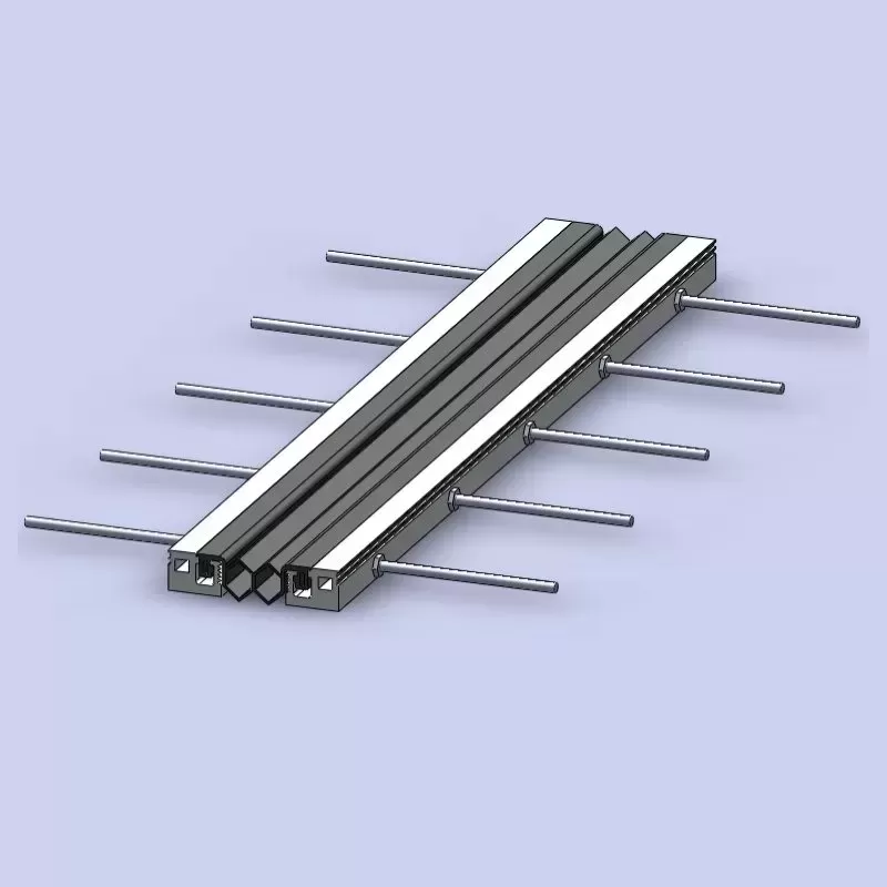
Strip seal systems are designed for small to medium movement ranges, typically accommodating up to 80 mm of total displacement. These assemblies consist of a preformed elastomeric profile secured between two steel edge rails. The steel profiles are anchored directly into the concrete deck utilizing welded studs or reinforcement anchor loops.
Waterproofing Integrity: The continuous elastomeric profile acts as a continuous membrane, preventing runoff water and corrosive deicing chemicals from reaching the substructure.
Geometric Versatility: These components can be fabricated to match complex bridge deck cross-sections, including vertical curbs, sidewalks, and skewed configurations.
Structural Simplicity: The straightforward mechanical design allows for rapid installation and simplified replacement of the elastomeric seal if physical damage occurs.
Modular Bridge Joints
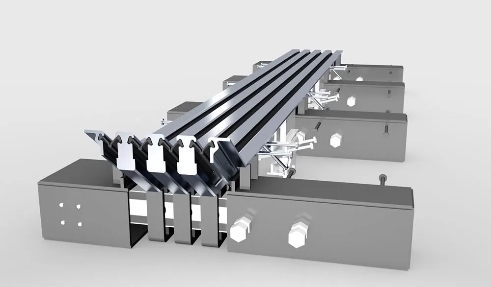
For structures requiring movement capacity exceeding 80 mm, modular designs represent the standard engineering solution. These complex mechanical assemblies utilize multiple elastomeric seals separated by intermediate steel beams, known as center beams. The entire assembly is supported by underlying crossbeams and control systems that distribute the structural displacement evenly across each individual seal gap.
Multi-Directional Movement: Modular systems accommodate not only longitudinal translation but also transverse displacement and vertical rotations.
Load Distribution: Heavily engineered support boxes house the crossbeams, transferring high dynamic wheel loads into the bridge deck reinforcement.
Elastic Control Systems: Internal compression springs and sliding bearings made of low-friction materials ensure uniform gap spacing during thermal cycles.
Finger and Cantilever Joint Assemblies
Finger joints are non-watertight or semi-watertight assemblies that use interlocking steel fingers to span the expansion gap. These systems are commonly specified for medium to long-span bridges where structural movement is primarily longitudinal.
High Riding Comfort: The interlocking design minimizes the gap width experienced by vehicle tires, significantly reducing noise emissions and impact vibrations.
Heavy-Duty Durability: Constructed from robust structural steel plates, these systems resist heavy snowplow operations and severe abrasive wear.
Drainage Management: Because the joint itself is open, a drainage trough made of durable synthetic rubber or stainless steel must be installed underneath to capture and redirect surface runoff.
Asphaltic Plug Joint Systems
Asphaltic plug systems provide a seamless, buried joint solution for movement ranges up to 50 mm. This design utilizes a specialized polymer-modified binder mixed with select aggregates, placed over a steel backing plate that spans the expansion gap.
Continuous Roadway Surface: Because there are no exposed metal components, these joints provide an exceptionally quiet transition and eliminate mechanical wear from tires.
Flexible Adhesion: The polymer binder retains elasticity across wide temperature ranges, preventing water infiltration while allowing structural contraction.
Rapid Installation: The material can be placed and cooled quickly, reducing traffic disruption during rehabilitation projects.
Parameters Guiding the Selection of Bridge Joints
Specifying the correct structural joint is not merely a function of calculating maximum thermal expansion. Structural designers must evaluate a matrix of interrelated factors to ensure the chosen system performs reliably over its intended design life.
First, movement capacity must be calculated using realistic boundary conditions. This calculation must account for thermal expansion and contraction, concrete creep and shrinkage, structural rotations under live loads, and potential seismic displacement. Underestimating these displacements can lead to over-extension of the elastomer or physical collision of the concrete spans during high-temperature periods.
Second, dynamic loading and fatigue resistance are highly important. Bridge joints are subjected to millions of cyclic impact loads from heavy commercial vehicles. The steel profiles, anchorage components, and welds must be designed to resist fatigue failure in accordance with international standards such as AASHTO LRFD or EN 1990. Poorly designed anchorages often suffer from concrete cracking and bond failure, leading to loose joints and subsequent structural damage.
Third, environmental exposure dictates material selection. Deicing chemicals, marine environments, UV radiation, and extreme temperature variations degrade low-quality materials. KINGWORK addresses these environmental factors by utilizing corrosion-resistant steel grades, hot-dip galvanizing, and advanced elastomeric compounds designed to maintain elasticity in sub-zero temperatures and resist ozone degradation.
Another factor to evaluate is the geometry of the bridge deck. Horizontal curvature, vertical gradients, and skew angles complicate joint design. The manufacturing team must customize the joint profile to match the exact cross-section of the bridge deck, including the barriers and sidewalks, to maintain a continuous, watertight seal.
.webp?t=1783324482860 "024")
Mitigating Common Performance Failures in Expansion Assemblies
To maintain structural durability, design engineers must understand the typical degradation mechanisms associated with bridge joints and implement preventive measures during the design phase.
Water leakage represents the most common cause of secondary structural deterioration. When a joint seal fails, water laden with deicing salts penetrates the expansion gap, dripping directly onto the underlying bearings, piers, and abutments. This accelerates the corrosion of structural steel girders and causes concrete spalling. Ensuring a continuous, durable seal profile is a primary defense against this form of degradation.
Debris accumulation within the joint gaps represents another operational challenge. Stones, sand, and road debris can pack tightly into the expansion openings. During thermal expansion cycles, this incompressible debris prevents the joint from closing fully, generating massive compressive stresses within the bridge deck. Regular inspection and the selection of self-cleaning seal profiles help mitigate this issue.
Anchorage zone degradation often occurs due to inadequate reinforcement detailing or poor concrete consolidation during installation. The transition zone between the flexible joint and the rigid concrete deck undergoes intense dynamic stresses. Applying polymer-modified concrete or high-strength non-shrink grouts in the blockout area ensures a durable bond and prevents localized structural failure under heavy wheel loads.
Precision Installation and Long-Term Maintenance Protocols
The longevity of any expansion assembly is heavily dependent on the quality of its installation. Even a perfectly designed joint will fail prematurely if installed incorrectly.
The installation process begins with the preparation of the blockout recess. The concrete surface must be clean, dry, and free of laitance. The joint assembly is then positioned in the gap, utilizing temporary setting devices that adjust the joint width according to the ambient temperature at the time of casting.
Aligning the joint flush with the finished road surface is mandatory. A deviation of even a few millimeters can create an impact step, significantly increasing the dynamic loads exerted on the joint by passing vehicles. Once the alignment is verified, the anchorage reinforcement is tied to the main deck reinforcement, and high-performance concrete is poured and consolidated.
Maintenance programs should include routine inspections at least twice a year, typically in extreme winter and summer conditions. Inspectors should check for:
Tears, punctures, or displacement in the elastomeric seals.
Loosening of anchorage components or visible cracking in the transition concrete.
Excessive debris buildup that hinders structural movement.
Signs of water leakage on the substructure elements beneath the joint.
Replacing worn elastomeric profiles in a timely manner is a cost-effective strategy that avoids the high expenses associated with complete structural replacement.
Engineering Cooperation and Inquiry Support
Selecting and customizing bridge joints requires specialized engineering expertise. KINGWORK provides comprehensive engineering support, from initial design consultation and structural analysis to custom manufacturing and installation guidance. Our engineering team designs solutions tailored to the specific movement ranges, load profiles, and environmental conditions of your project.
For engineering specifications, standard drawings, or to discuss the requirements of an upcoming infrastructure project, please contact our engineering division for a detailed consultation and inquiry response.
Frequently Asked Questions
Q1: What are the primary differences between strip seal and modular bridge joints?
A1: Strip seal joints utilize a single elastomeric seal and are limited to movements up to 80 mm. Modular joints use multiple seals separated by steel center beams and support bars, allowing them to accommodate large multi-directional displacements exceeding 1,000 mm.
Q2: How does temperature affect the installation of expansion joints?
A2: The width of the expansion gap changes with ambient temperature. During installation, the preset width of the joint assembly must be adjusted to match the exact bridge deck temperature at the time of concrete casting to ensure the system can expand and contract within its designed limits.
Q3: Why is waterproofing such a high priority for bridge joints?
A3: Waterproofing protects the underlying substructure. If water penetrates the joint, it causes rapid corrosion of the steel reinforcement, bearings, and steel girders, leading to costly structural rehabilitation work.
Q4: Can modular bridge joints be repaired without replacing the entire assembly?
A4: Yes, individual components such as elastomeric profiles, sliding bearings, and control springs can often be replaced during scheduled maintenance windows, provided the main steel structural frame and anchorage system remain intact.
Q5: What materials are typically used to manufacture durable elastomeric seals?
A5: High-quality elastomeric seals are manufactured using neoprene (chloroprene) or EPDM compounds. These materials offer high resistance to ozone degradation, UV radiation, extreme temperatures, and chemical exposure from deicing salts.
![Bridge Joint Types: The Complete Engineering Guide [2026 Edition]](https://www.kwbridgebearing.com/storage/non_theme/202606/024.webp)